Background
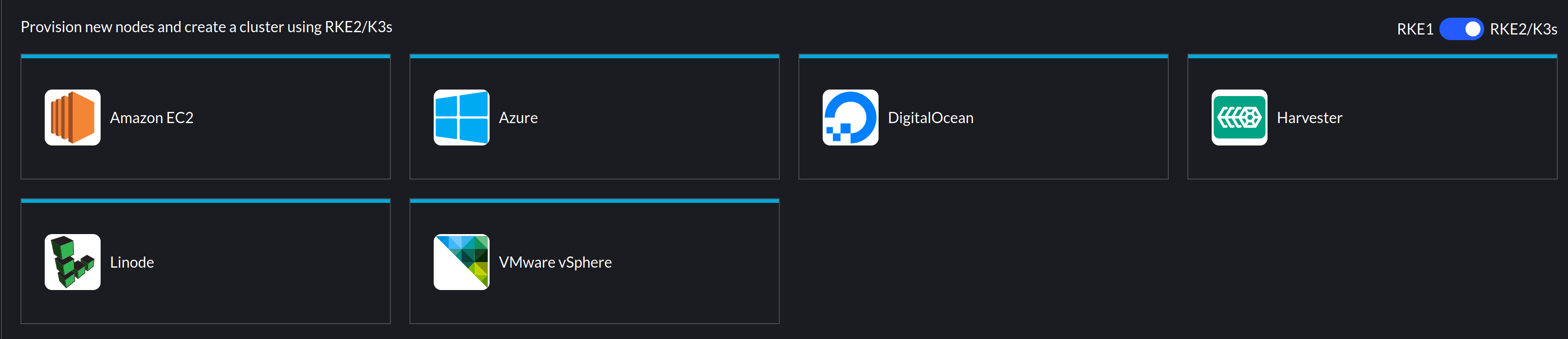
Rancher leverages cloud-init for the provisioning of Virtual Machines on a number of infrastructure providers, as below:
I recently encountered an issue whereby vSphere based clusters using an Ubuntu VM template would successfully provision, but SLES based VM templates would not.
What does Rancher use cloud-init for?
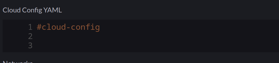
This is covered in the Masterclass session I co-hosted, but as a refresher, particularly with the vSphere driver, Rancher will mount an ISO image to the VM to deliver the user-data portion of a cloud-init configuration. The contents of which look like this:
#cloud-config
groups:
- staff
hostname: scale-aio-472516f5-s82pz
runcmd:
- sh /usr/local/custom_script/install.sh
set_hostname:
- scale-aio-472516f5-s82pz
users:
- create_groups: false
  groups: staff
  lock_passwd: true
  name: docker
  no_user_group: true
  ssh_authorized_keys:
  - |
    ssh-rsa AAAAB3NzaC1yc.......
  sudo: ALL=(ALL) NOPASSWD:ALL
write_files:
- content: H4sIAAAAAAAA/wAAA...........
  encoding: gzip+b64
  path: /usr/local/custom_script/install.sh
  permissions: "0644"
Note: This is automatically generated, any additional cloud-init config you include in the cluster configuration (below) gets merged with the above.
It saves a script with write_files and then runs this with runcmd – this will install the rancher-system-agent service and begin the process of installing RKE2/K3s.
The Issue
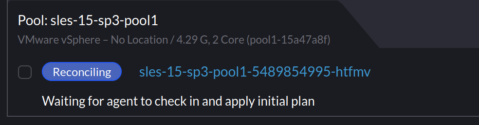
When I provisioned SLES based clusters using my existing Packer template, Rancher would indicate it was waiting for the agent to check in:
Investigating
Thinking cloud-init didn’t ingest the config, I ssh’d into the node to do some debugging. I noticed that the node name had changed:
sles-15-sp3-pool1-15a47a8f-xcspb:~ #
Which I verified with:
sles-15-sp3-pool1-15a47a8f-xcspb:/ # cat /var/lib/cloud/instance/user-data.txt | grep hostname
hostname: sles-15-sp3-pool1-15a47a8f-xcspb
Inspecting user-data.txt from that directory also matched what was in the mounted ISO. I could also see /usr/local/custom_script/install.sh was created, but nothing indicated that it was executed. It appeared everything else from the cloud-init file was processed – SSH keys, groups, writing the script, etc, but nothing from runcmd was executed.
I ruled out the script by creating a new cluster and adding my own command:
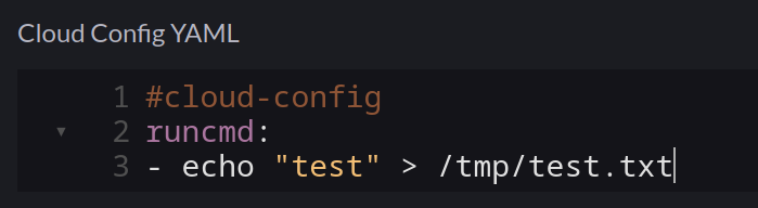
As expected, this was merged into the user-data.iso file mounted to the VM, but /tmp/test.txt didn’t exist, so it was never executed.
Checking cloud-init logs
Cloud-Init has an easy way to collect logs – the cloud-init collect-logs command, This will generate a tarball:
sles-15-sp3-pool1-15a47a8f-xcspb:/ # cloud-init collect-logs
Wrote /cloud-init.tar.gz
I noted in cloud-init.log I could see the script file being saved:
2023-01-18 09:56:22,917 - helpers.py[DEBUG]: Running config-write-files using lock (<FileLock using file '/var/lib/cloud/instances/nocloud/sem/config_write_files'>)
2023-01-18 09:56:22,927 - util.py[DEBUG]: Writing to /usr/local/custom_script/install.sh - wb: [644] 29800 bytes
2023-01-18 09:56:22,928 - util.py[DEBUG]: Changing the ownership of /usr/local/custom_script/install.sh to 0:0
But nothing indicating it was executed.
I decided to extrapolate a list of all the cloud-init modules that were initiated:
cat cloud-init.log | grep "Running module"

stages.py[DEBUG]: Running module migrator
stages.py[DEBUG]: Running module seed_random
stages.py[DEBUG]: Running module bootcmd
stages.py[DEBUG]: Running module write-files
stages.py[DEBUG]: Running module growpart
stages.py[DEBUG]: Running module resizefs
stages.py[DEBUG]: Running module disk_setup
stages.py[DEBUG]: Running module mounts
stages.py[DEBUG]: Running module set_hostname
stages.py[DEBUG]: Running module update_hostname
stages.py[DEBUG]: Running module update_etc_hosts
stages.py[DEBUG]: Running module rsyslog
stages.py[DEBUG]: Running module users-groups
stages.py[DEBUG]: Running module ssh
But still, no sign of runcmd.
Checking cloud-init configuration
Outside of the log bundle, /etc/cloud/cloud.cfg includes the configuration for cloud-init. having suspected the runcmd module may not be loaded, I checked, but it was present:
# The modules that run in the 'config' stage
cloud_config_modules:
 - ssh-import-id
 - locale
 - set-passwords
 - zypper-add-repo
 - ntp
 - timezone
 - disable-ec2-metadata
 - runcmd
However, I noticed that nothing from the cloud_config_modules block was mentioned in cloud-init.log. However, everything from cloud_init_modules was:
# The modules that run in the 'init' stage
cloud_init_modules:
 - migrator
 - seed_random
 - bootcmd
 - write-files
 - growpart
 - resizefs
 - disk_setup
 - mounts
 - set_hostname
 - update_hostname
 - update_etc_hosts
 - ca-certs
 - rsyslog
 - users-groups
 - ssh
So, it appeared the entire cloud_config_modules step wasn’t running. Weird.
Fixing
After speaking with someone from the cloud-init community, I found out that there are several cloud-init services that exist on a host machine. Each dedicated to a specific step.
Default config on SLES 15 SP4 machine:
sles-15-sp3-pool1-15a47a8f-xcspb:/ # sudo systemctl list-unit-files | grep cloud
cloud-config.service                    disabled        disabled
cloud-final.service                     disabled        disabled
cloud-init-local.service                disabled        disabled
cloud-init.service                      enabled         disabled
cloud-config.target                     static          -
cloud-init.target                       enabled-runtime disabled
Default config on a Ubuntu 22.04 machine:
packerbuilt@SRV-RNC-1:~$ sudo systemctl list-unit-files | grep cloud
cloud-config.service                        enabled         enabled
cloud-final.service                         enabled         enabled
cloud-init-hotplugd.service                 static          -
cloud-init-local.service                    enabled         enabled
cloud-init.service                          enabled         enabled
cloud-init-hotplugd.socket                  enabled         enabled
cloud-config.target                         static          -
cloud-init.target                           enabled-runtime enabled
The cloud-config service was not enabled and therefore would not run any of the related modules. To rectify, I added the following to my Packer script when building the template:
# Ensure cloud-init services are enabled
systemctl enable cloud-init.service
systemctl enable cloud-init-local.server
systemctl enable cloud-config.service
systemctl enable cloud-final.service
After which, provisioning SLES based machines from Rancher worked.