Virtual Thoughts

Virtualisation, Storage and various other ramblings.

Page 23 of 24

An introduction to vSphere Metro Storage Cluster with Compellent Live Volume

Intro

VMware vSphere Metro Storage Cluster is a suite of infrastructure configurations that facilitate a stretched cluster setup. It’s not a feature like HA/DRS that we can switch on easily; it requires architectural design decisions that specifically contribute to this configuration. The foundation of which are stretched clusters and with regards to the Compellent suite of solutions Live Volume

Stretched Cluster

Stretched clusters are pretty much self explanatory. In comparison to a lot of configurations where compute clusters reside within the same physical room, stretched clusters spread the compute capacity over more than one physical location. This can still be internally (different server rooms within the same building) or further apart over geographically disperse sites.

Having stretched clusters gives us greater flexibility and potentially better RPO/RTO with mission critical workloads when implemented correctly. Risk and performance are spread across one location. Failover scenarios can be further enhanced with automatic fail over features that come with solutions like Compellent Live Volume.

From a networking perspective. Ideally we have a stretched & trunked layer 2 network across both sites facilitated by redundant connections. I will touch on requirements later on in this post.

What is Live Volume?

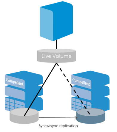
Live volume is a specific feature with Dell Compellent storage centers. Broadly speaking  Live Volume virtualizes the volume presentation separating it from disk and RAID groups within each storage system. This virtualization enables decoupling of the volume presentation to the host from its physical location on a particular storage array. As a result, promoting the secondary storage array to primary status is transparent to the hosts, and can be done automatically with auto-failover. Why is this important for vMSC? Because in certain failure scenarios we can fail over between both sites automatically and gracefully.


LV


Requirements

Specifically regarding the Dell Compellent solution:

  • SCOS 6.7 or newer
  • High Bandwidth, low latency link between two sites
    • Latency must be no greater than 10ms. 5ms or less is recommended
    • Bandwidth is dependent on load, it is not uncommon to see redundant 10Gb/40Gb links between sites
  • Uniform or non-uniform presentation
  • Fixed or round Robin path selection
  • No support for Physical Mode RDM’s
    • Very important when considering traditional MSCS
  • For auto failover a third site is required with the Enterprise Manager software installed to act as a a tiebreaker
    • Maximum latency to both storage center networks must not exceed 200ms RTT
  • Redundant vMotion network supporting minimum throughput of 250Mbps


Presentation Modes – Uniform

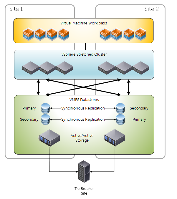
For vMSC we have two options for presenting our storage. Uniform and Non uniform. Below is a diagram depicting a traditional uniform configuration. Uniform configurations are commonly reffered to as “mesh” typologies, because of how the compute layer has access to primary and secondary storage both locally and via the inter-site link.


uniform


Key considerations about uniform presentation:

  • Both Primary and Secondary Live Volumes presented on active paths to all ESXi hosts.
  • Typically used in environments where both sites are in close proximity.
  • Greater pressure/dependency on inter-site link compared to non-uniform.
  • Different reactions to failure scenarios compared to non-uniform – Because of storage paths and how Live volume works
  • Attention needs to be taken to IO paths. For example, write requests received by a storage center that holds the secondary volume will simply act as a proxy and redirect the I/O request to the Storage Center that has the primary volume over the replication network. This causes additional delay. Under some conditions, Live volume will be intelligent enough to swap the roles for a volume when it experiences all I/O requests from a specific site.


Presentation Modes – Non Uniform

Non-Uniform presentation restricts primary volume access to the confines of the local site. Key differences and observations are around how vCenter/ESXi will react to certain failure scenarios. It could be argued that non-uniform presentation isn’t as resilient as uniform, but this depends on the implementation.non-uniform

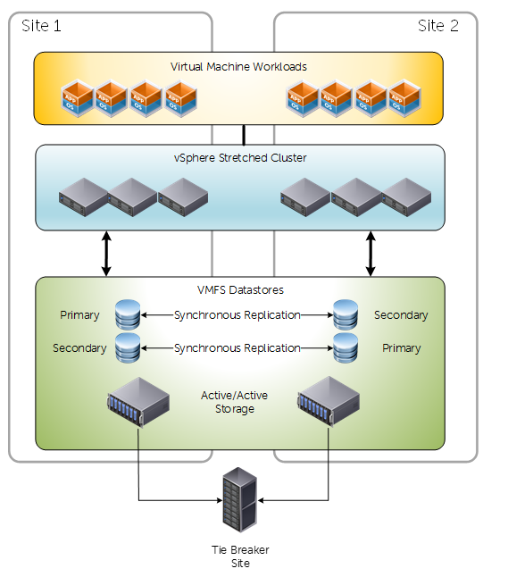
Key considerations about Non-uniform presentation:

  • Primary and Secondary Live Volumes presented via active paths to ESXi hosts within their local site only
  • Typically used in environments where both sites are not in close proximity
  • Less pressure/dependency on inter-site connectivity
  • Path/Storage failure would invoke a “All Paths Down” condition. Consequently affected VM’s will be rebooted on secondary site. Whereas compared to uniform presentation they would not – because paths would still be active.


Synchronous Replication Types

With Dell Compellent storage centers we have two methods of achieving synchronous replication:

  • High Consistency
    • Rigidly follows storage industry specifications pertaining to synchronous replication.
    • Guarantees data consistency between replication source and target.
    • Sensitive to Latency
    • If writes cannot be committed to destination target, it will not be committed at the source. Consequently the IO will appear as failed to the OS.
  • High Availability
    • Adopts a level of flexibility when adhering to industry specifications.
    • Under normal conditions behaves the same as High Consistency.
    • If the replication link or the destination storage either becomes unavailable or exceeds a latency threshold, Storage Center will automatically remove the dual write committal requirement at the estination volume.
    • IO is then Journaled at the source
    • When destination volume has returned healthy, IO is flushed at the destination

Most people tend to opt for High Availability mode for flexibility, unless they have some specific internal or external regulatory requirements.


Are there HA/DRS considerations?

Short answer, yes. Long answer, it depends on the storage vendor, but as this is a Compellent-Centric post I wanted to discuss a (really cool) feature that can potentially alleviate some headaches. It doesn’t absolve all HA/DRS considerations, because these are still valid design factors.

FO


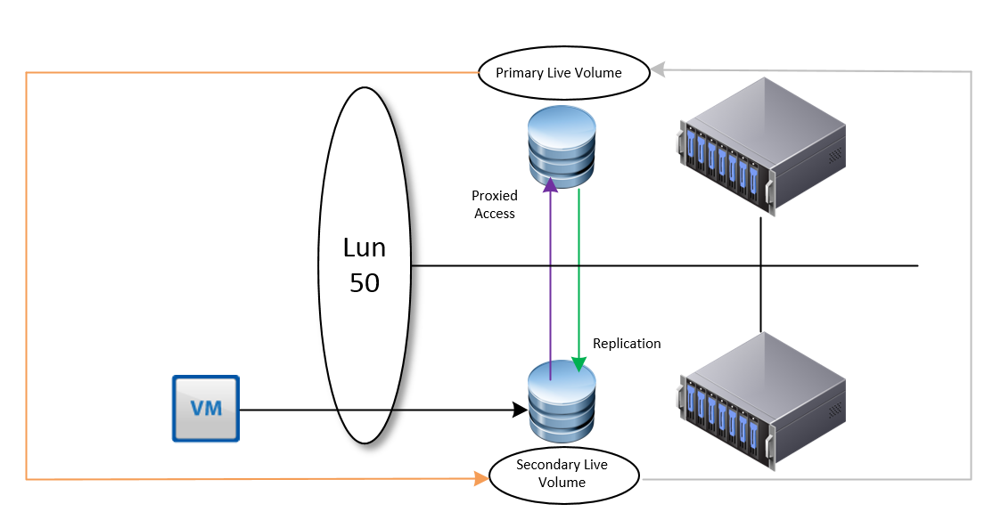
In this example we have a Live Volume configured on two SAN’s leveraging Synchronous replication in a uniform presentation.

If, for any reason a VM is migrated to the second site where the secondary volume resides, we will observe IO requests proxied over to the storage center that currently has the primary live volume.

However, Live volume is intelligent enough to identify this, and under these conditions will perform a automatic role swap, in an attempt to make all IO as efficient as possible.

I really like this feature, but it will only be efficient if a VM has its own volume, or VM’s that reside on one volume are grouped together. If Live Volume sees IO from both sites to the same Live Volume, then it will not perform a role swap. Prior to this feature, and under different design considerations we would need to leverage DRS affinity rules (should, not must) for optimal placement of VM’s for the shortest path of IO.

Other considerations include, but not limited to:

  • Admission Control
    • Set to 50% to allow enough resource for complete failover
  • Isolation Addresses
    • Specify two, one for each physical site
  • Datastore Heartbeating
    • Increase the number of datastore heartbeats from two to four in a stretched cluster. Two DS’s for each site


Why we need a third site

Live volume can work without a third site, but you won’t get automatic failover. It’s integral for establishing quorum during unplanned outages and for preventing split brain conditions during networking partitioning. With Compellent, we just need to install the Enterprise Manager on a third site that has connectivity to both storage centers, <200ms latency and it can be a physical or virtual Windows machine.


Conclusion

As you can imagine a lot of care and attention is required when designing and implementing a vMSC solution. Compellent has some very useful features to facilitate it, and with advancements in network technology there is a growing trend for stretched clusters for many reasons.

Facilitating multi-SAN Environments

The what, where and why

At the moment I’m involved in a fair amount of project work involving data (VM) migrations between different storage platforms, sometimes even from the same vendor. What seems to be quite a simple process can get complicated depending on the design considerations for both storage platforms and the migration criteria – particularly if both storage platforms need to co-exist for either the short or long term and migrated VM’s must be performed live.


But we have shared nothing vMotion for this, right?

Yes and No. A lot of administrators don’t like to work with multiple SAN environments – and with good reason. Conflicting design considerations (which I will touch on later) can cause some incompatibility depending on your host configuration (think iSCSI port bindings as an example). For some migrations it’s perfectly acceptable to (for example) logically segment ESXi hosts that belong to different SAN environments and simply vMotion across. Once you’ve migrated everything across reconfigure all hosts to see the new, shiny storage platform only.

However, requirements I’ve received recently from various customers stipulate that both SAN environments must co-exist on all hosts in a supported fashion. Some for sort term migrations, others for mid term (maybe to keep the old storage environment for test/dev). These clients have a small number of densely populated hosts, and therefore do not want segmentation of hosts (ie cluster A = SANA, cluster B = SANB).

So how can we facilitate this?

Assess design considerations for the existing SAN

All storage vendors will (or should) have existing documentation pertaining to best practice for implementing their flavor of storage array. As an example I’ll pick the Dell EqualLogic as I’m quite familiar with it.

The EqualLogic is an active/passive storage device, commonly implemented in VMware environments by leveraging the Software iSCSI initiator. We then create either one vSwitch with two VMKernel port groups for iSCSI, each having their own dedicated NIC and the rest being unused, or two vSwitches with 1 VMKernel port group each, with their own dedicated NIC and the rest being unused. IP addresses for all initiators and the target reside on the same VLAN/Subenet Range, so iSCSI port binding is used.

Assess design considerations for the new SAN

Commonplace at the moment are new 10Gb iSCSI SANs being implemented, including new NICs/HBA’s into hosts, switches and obviously the storage device itself. As an example I was asked to co-exist a EqualLogic (1Gb) with another storage device (10Gb) that had different design considerations:

The new storage device is an active/active device, with best practice dictating that each storage controller reside on its own VLAN/Subnet range.

Assessing how to configure hosts to support both SAN environments

In the example previously described we have a particular issue:

  • Existing configuration involves iSCSI port binding with all participating initiators and targets in the same VLAN.

This is perfectly common and acceptable with the EqualLogic. But this cannot support the new storage device. Although we technically *could* modify the existing binding to accommodate the new SAN, this will cause issues and is by in large not supported. https://kb.vmware.com/selfservice/microsites/search.do?language=en_US&cmd=displayKC&externalId=2038869. Even if we put the new storage device on the same VLAN as the EqualLogic, it still isn’t a good idea. Single targets should really be used and including mixed, speed nics in iSCSI port binding is a very bad idea.

Simply put, we can not, and should not modify the existing iSCSI port bindings. We can only have 1 software iSCSI initiator, and when we use port binding it will not leverage other VMKernel port groups.

This leaves us with two options:

Option #1 iSCSI-Independent HBA’s

Independent HBA’s do not rely upon ESXi for configuration parameters. They’re configured outside of the operating system. This is probably the better way of achieving segmentation between multiple SAN environments. This way we have independent HBA’s facilitating traffic to the new storage array, and existing NICs in the existing iSCSI port binding facilitating traffic to the existing storage array.

Option #2 iSCSI-Dependent HBA’s

I’m honestly not sure if it’s just a demand thing, or if people are finding acceptable levels of performance from software iSCSI implementations (I know I am) but I don’t really come across dedicated iSCSI Independent HBA’s anymore. I’d imagine they represent a bit of a false economy with the limited number of PCI-Express slots of small servers these days.

Converged network adapters on the other hand I find very common. For those that are not aware, CNA’s are like multi-personality NICs. They’re presented in ESXi as both regular NIC’s and iSCSI (and/or FCoE) storage adapters with the same MAC. They are usually considered iSCSI-Dependent NIC’s though.

iSCSI

What we’re able to do here is create our vmkernel ports for the new storage array (one for each uplink for our active/active array) on different VLAN’s, IP address ranges etc. Then assign one to each of our iSCSI uplinks and off we go. We still achieve separation of traffic because the software iSCSI initiator remains untouched, and traffic to the new SAN is facilitated by different nics, VMK’s, etc.

It’s important to identify there that VMware does support using mixed software AND hardware iSCSI initiators but not to the same target.

Option #3 – Swing Host

I’ve heard people using these before. They’re essentially a designated host that’s configured with perhaps not a supported or best practice configuration, but is homed to both SAN environments and is just used for migration purposes. You essentially VMotion a VM onto this host, do what you need to do with it, and vMotion it off again to a supported host.

It often works, but is considered a “quick and dirty” solution to this problem, and unlikely to receive any official support from both VMware and your storage vendor.

Conclusion

Hopefully this might help others who may be tasked with a similar requirement. It’s not ideal, and as I mentioned before we try and not implement multi SAN-environments where possible. But sometimes we have to. What’s important is to implement something that is supported and stable.


In-guest iSCSI to native VMDK

Do we really need in-guest iSCSI volumes?

Well, yes and no.

I’ll admit, the need for VM’s with their own iSCSI initiator have decreased over the various improvements made to vSphere and ESXi. However, I would imagine there are a number of implementations that (justifiably)  still need this arrangement, and those that don’t. I was recently tasked with eliminating a number of guest-initiated iSCSI disks in favor of using native VMDK’s.

I’m sure a lot of VMware admins have either gone through this process, or will find themselves with this task at some point. This post serves as a rough guide to my approach – which doesn’t necessarily mean that it’s the only way to do this, but it worked for me.

Idea #1 – VMware Converter

VMware Converter is an easy piece of software to use. Pick a source, pick a destination, modify the properties of the associated disks. Et Voila! However, one of the main considerations to make when using this is the maintenance window involved. If you’re converting a number of virtual disks, particularly to the same storage array, then you’ll need a sizeable disk space overhead, as you may have to essentially mirror all the data before you can delete the source. This also takes time

Idea #2 – OS Native File Copy to a VMDK

The principle behind this is quite easy. As an example, a file server VM could have a in-guest iSCSI volume to hold all share data. A VMDK could be created and added to the VM, then we can robocopy/rsync the data across and re-configure sharing etc. Again, similar with Idea #1 there are space considerations to factor for, as you’re duplicating data for a short period.

Idea #3 – Convert the disk to a VMDK

This idea differs from the previous two by converting the drive that currently holds the data into a native VMDK. There’s no need to mirror/duplicate the data, but there’s still a maintenance window involved.

Idea #3 seemed most suitable for me. Duplicating data would take up too much space, put extra strain on my SAN, and should anything go a miss I always have decent backups to restore from. So lets go a bit more in depth on how we convert a in-guest iSCSI volume in to a native VMDK.

Overview – Idea #3 fleshed out

There’s no single-step process to convert a in-guest iSCSI volume into a native VMDK. We can do it by following the following conversion process
VMDK

We must (at time of writing) convert the in-guest iSCSI volume to a virtual mode RDM, at which point we can then Storage vMotion (sVMotion) it to a native VMDK. Below is my approach at doing so:


Step #1 – Find out what services are touching the drive we want to convert

Some VM’s will be easier than others when it comes to finding this out. Some drives are dedicated to specific services such as SQL server. We need to know which because we want to be careful with data consistency. If unsure, we can use tools such as handle.exe from Microsoft Sysinternals which will give us an idea as to which files are currently being used:


Handle

In this example E:\ was my mapped iSCSI volume. Executing handle.exe |findstr /i e:\ revealed which files on E:\ had active file handles. This can also be accomplished by Process Explorer too. Next we shut down the services that have handles to this drive. So in this example I shut down SQL server.


Step #2 – Disconnect all iSCSI based volumes, disable iSCSI vNIC’s and shutdown the VM

  1. Log into the Virtual Machine.
  2. Open the “Disk Management” MMC snapin.
  3. Right click the drive representing the in-guest iSCSI volume and select “offline”.
  4. The disk should no longer be mounted.
  5. Launch the iSCSI initiator and select the “Targets” tab.
  6. Select the target that’s currently connected and click “Disconnect”.
  7. The volume should be listed as Inactive and no longer visible from “Disk Management”.
  8. In Network Connections disable the iSCSI NIC.
  9. Shut down the VM.


Step #3 – Present previously used in-guest volume to ESXi hosts

We need to do this so we can add the volume as a Virtual Mode RDM to the VM. How we accomplish this depends on your storage vendor. But as a top level overview:

  1. Log in to SAN management application
  2. Modify the existing volume access policies so volume is visible to all ESXi hosts by authentication methods such as Access Policy / CHAP / initiator name / IP address /etc


Step #4 – Add volume as a Virtual Mode RDM to VM

  1. Perform a rescan of the ESXi host HBA’s so the newly presented volume is visible.
  2. Right click VM > Edit Settings.
  3. Add new Device > Hard Disk > Click Next.
  4. Select Raw Device Mapping as the Disk Type.
  5. Select the volume from the list.
  6. Select a datastore use to map this volume. Click Next.
  7. Select “Virtual” as the compatibility mode. Click Next.
  8. Leave advanced options as-is, unless required. Click Next.
  9. Click finish.
  10. Click OK to commit the VM configuration changes


Step #5 – Power on VM and check data integrity

  1. Power on the VM.
  2. Open “Disk Management”.
  3. Right click the added volume and select the “Online” option.
  4. Check drive contents (The volume should be mapped with the previous volume label/drive letter).


Step #6 – Re-enable services that require access

Opposite of step 1.


Step #7 – Storage vMotion disk and change disk type

  1. Right click the VM in vSphere and select “Migrate”.
  2. Select “Change datastore” and click “next”.
  3. Click the “Advanced” button.
  4. Select the appropriate datastore for the RDM disk and change the disk format from “Same Format as source” to “Thin/Thick Provision”. Other drives remain unchanged (ie OS drive).
  5. Click Next.
  6. Click Finish
  7. Wait until the storage vMotion has completed.
  8. Validate the vMotion by viewing the settings of the VM and checking the aforementioned drive is listed as a standard thin/thick provisioned vmdk and not a RDM

Step #8 – Cleanup

At this point we have finished our conversion process and can clean up by removing any integration tools from the VM, removing the iSCSI vNIC and deleting the volume originally used from the SAN.

« Older posts Newer posts »

© 2025 Virtual Thoughts

Theme by Anders NorenUp ↑

Social media & sharing icons powered by UltimatelySocial
RSS
Twitter
Visit Us
Follow Me