As a workaround, I experimented with writing an image directly to a PVC which can then be cloned/mounted to a KubeVirt VM. This example dd's an ISO image to a PVC:
Red Hat Openshift Virtualisation provides a platform for running and managing Virtual Machines alongside Containers using a consistent API. It also provides a mechanism for migrating VMs from platforms such as vSphere.
As I have both environments, I wanted to deploy an Openshift Virtualisation setup that mimics my current vSphere setup so I could migrate Virtual Machines to it.
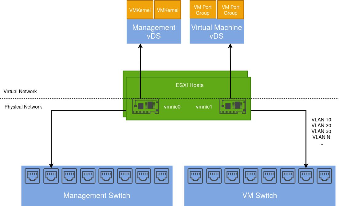
Existing vSphere Design
Below is a diagram depicting my current vSphere setup. My ESXi hosts are dual-homed with a separation of management (vmkernel) and virtual machine traffic.
vmnic1 is connected to a trunk port accommodating several different VLANs. These are configured as corresponding port groups in the Distributed Switch.
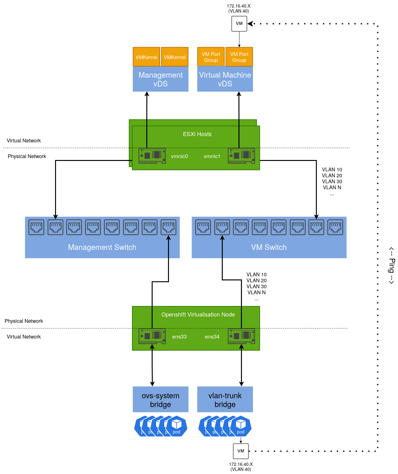
Integrating an Openshift Virtualisation host
Given an Openshift host with the same number of NICs, we can design a similar solution including a test use case:
By default, an existing bridge (ovs-system) is created by Openshift to facilitate cluster networking. To achieve the same level of isolation configured in the vSphere environment, an additional bridge is required. This will be called vlan-trunk and as the name implies, it will act as a trunk interface for a range of VLAN networks.
Once configured, a Virtual Machine Instance can be created, connected to one of these VLAN networks and reside on the same L2 network as their vSphere-managed VM counterparts.
Configuring the Openshift Node
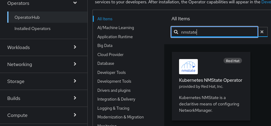
There are several ways to accomplish this, however for ease, the NMState Operator can be used to configure host networking in a declarative way:
Once installed, a default NMState object needs to be created:
After which we can define an instance of the NodeNetworkConfigurationPolicy object that creates our additional bridge interface and includes a specific NIC.
apiVersion: nmstate.io/v1
kind: NodeNetworkConfigurationPolicy
metadata:
  name: vlan-trunk-ens34-policy
spec:
  desiredState:
    interfaces:
      - name: vlan-trunk
        description: Linux bridge with ens34 as a port
        type: linux-bridge
        state: up
        ipv4:
          enabled: false
        bridge:
          options:
            stp:
              enabled: false
          port:
            - name: ens34
To validate, run ip addr show on the host:
2: ens33: <BROADCAST,MULTICAST,ALLMULTI,UP,LOWER_UP> mtu 1500 qdisc mq master ovs-system state UP group default qlen 1000
    link/ether 00:50:56:bb:e3:c3 brd ff:ff:ff:ff:ff:ff
    altname enp2s1
3: ens34: <BROADCAST,MULTICAST,UP,LOWER_UP> mtu 1500 qdisc mq master vlan-trunk state UP group default qlen 1000
    link/ether 00:50:56:bb:97:0d brd ff:ff:ff:ff:ff:ff
    altname enp2s2

...

653: vlan-trunk: <BROADCAST,MULTICAST,UP,LOWER_UP> mtu 1500 qdisc noqueue state UP group default qlen 1000
    link/ether 00:50:56:bb:97:0d brd ff:ff:ff:ff:ff:ff
In a similar way that Distributed Port groups are created in vSphere, we can create NetworkAttachmentDefinition objects that represent our physical network(s) in software.
The example below is comparable to a Distributed Port Group in vSphere that’s configured to tag traffic with the VLAN ID of 40. If required, we could repeat this process for each VLAN/Distributed Port group so we have a 1:1 mapping between both the vSphere and Openshift Virtualisation environments.
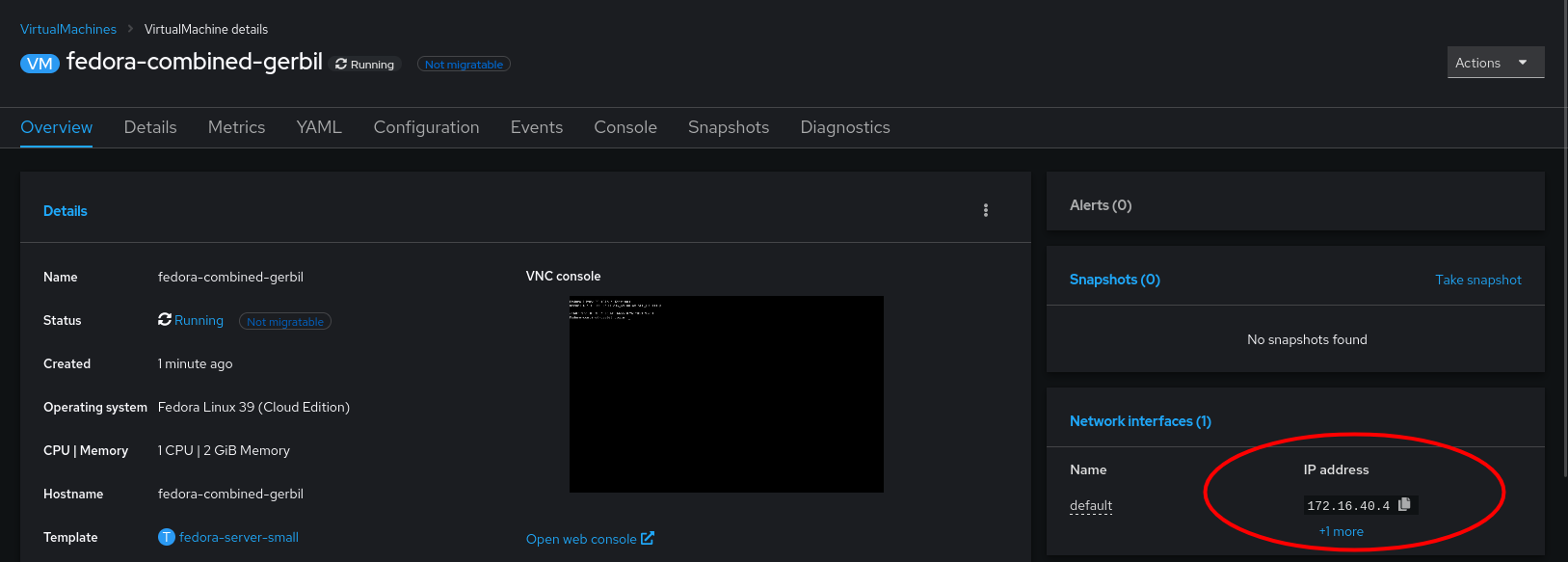
After a short period, the VM’s IP address will be reported to the console. In my example, I have a DHCP server running on that VLAN, which is how this VM acquired its IP address:
Which we can test connectivity from another machine with ping. such as a VM running on an ESXi Host:
sh-5.1# ping 172.16.40.4
PING 172.16.40.4 (172.16.40.4) 56(84) bytes of data.
64 bytes from 172.16.40.4: icmp_seq=1 ttl=63 time=1.42 ms
64 bytes from 172.16.40.4: icmp_seq=2 ttl=63 time=0.960 ms
64 bytes from 172.16.40.4: icmp_seq=3 ttl=63 time=0.842 ms
64 bytes from 172.16.40.4: icmp_seq=4 ttl=63 time=0.967 ms
64 bytes from 172.16.40.4: icmp_seq=5 ttl=63 time=0.977 ms
By taking this approach, we can gradually start migrating VM’s from vSphere to Openshift Virtualisation with minimal disruption, which I will cover in a subsequent post.
Disclaimer – The use of nested virtualisation is not a supported topology
Harvester is an open-source HCI solution aimed at managing Virtual Machines, similar to vSphere and Nutanix, with key differences including (but not limited to):
Fully Open Source
Leveraging Kubernetes-native technologies
Integration with Rancher
Testing/evaluating any hyperconverged solution can be difficult – It usually requires having dedicated hardware as these solutions are designed to work directly on bare metal. However, we can circumvent this by leveraging nested virtualisation – something which may be familiar with a lot of homelabbers (myself included) – which involves using an existing virtualisation solution provision workloads that also leverage virtualisation technology.
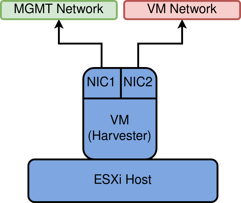
Step 1 – Planning
To mimic what a production-like system may look like, two NICs will be leveraged – one that facilitates management traffic, and the other for Virtual Machine traffic, as depicted below
MGMT network and VM Network will manifest as VDS Port groups.
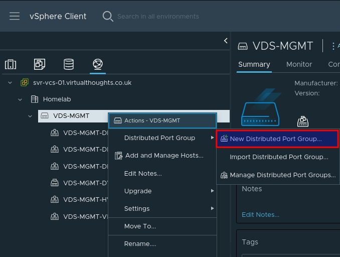
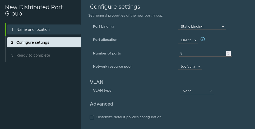
It is highly recommended to create new Distributed Port groups for this exercise, mainly because of the configuration we will be applying in the next step.
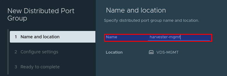
Create a new vDS Port Group:
Give the port group a name, such as harvester-mgmt
Adjust any configuration (ie VLAN ID) to match your environment (if required). Or accept the defaults:
Repeat this process to create the harvester-vm Port group. We should now have two port groups:
harvester-mgmt
harvester-vm
Step 3 – Enable MAC learning on Port groups [Critical]
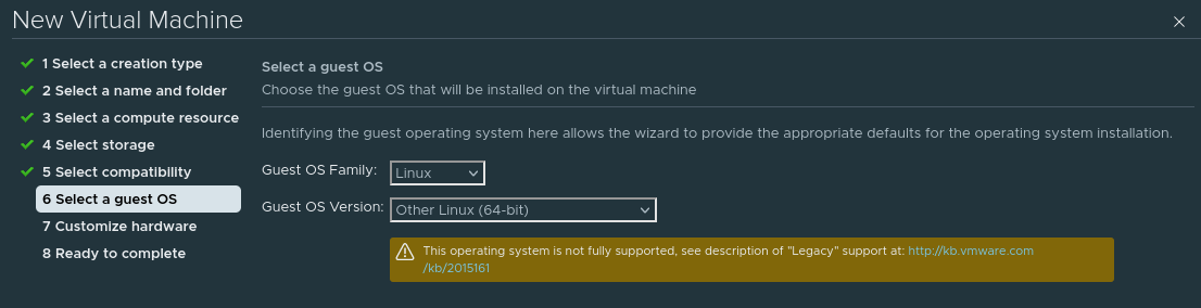
Our Harvester VM will operate like any other VM, with some important differences. In vSphere, go through the standard VM creation wizard to specify the Host/Datastore options. When presented with the OS type, select Other Linux (64 bit).
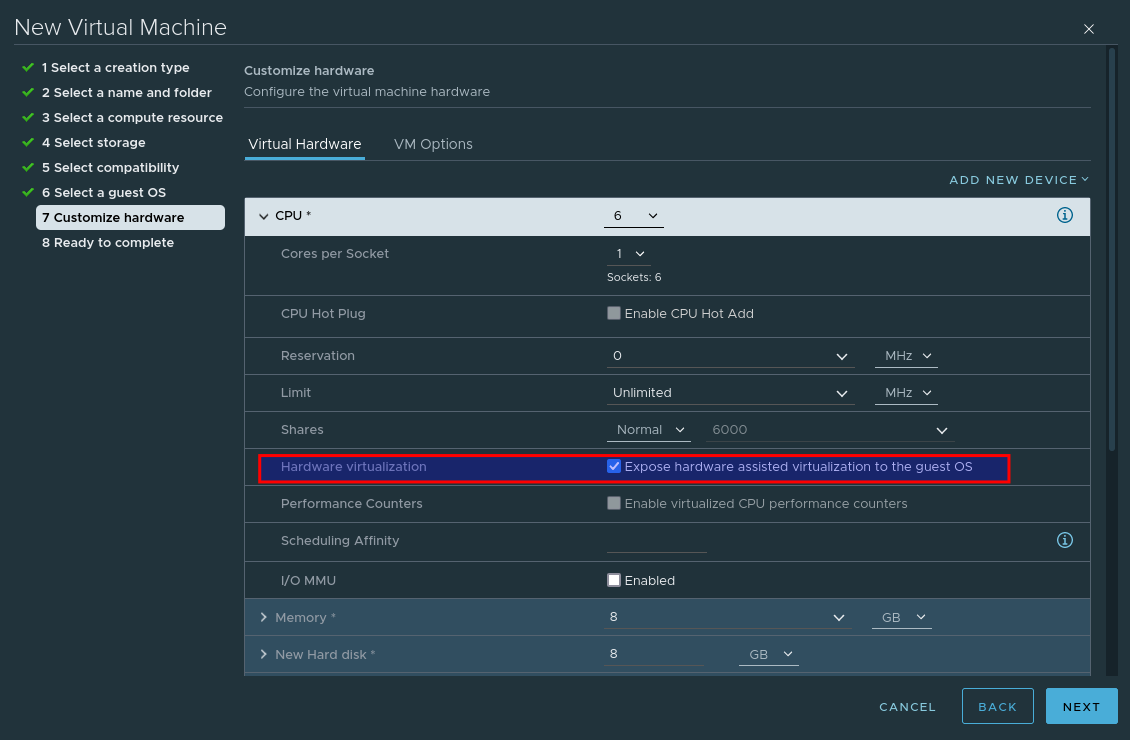
When customising the hardware, select Expose hardware assisted virtualization to the guest OS – This is crucial, as without this selected Harvester will not install.
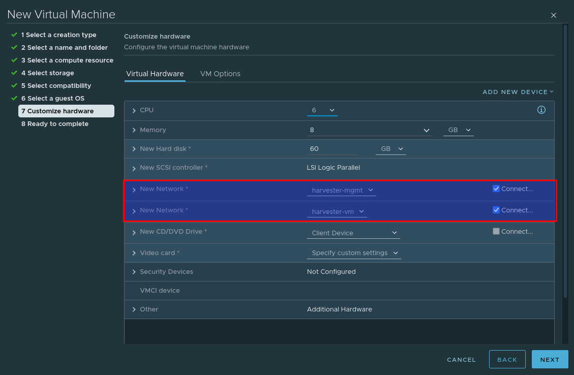
Add an additional network card so that our VM leverages both previously created port groups:
And finally, mount the Harvester ISO image.
Step 4 – Install Harvester
Power on the VM and providing the ISO is mounted and connected, you should be presented with the install screen. As this is the first node, select create a new Harvester Cluster
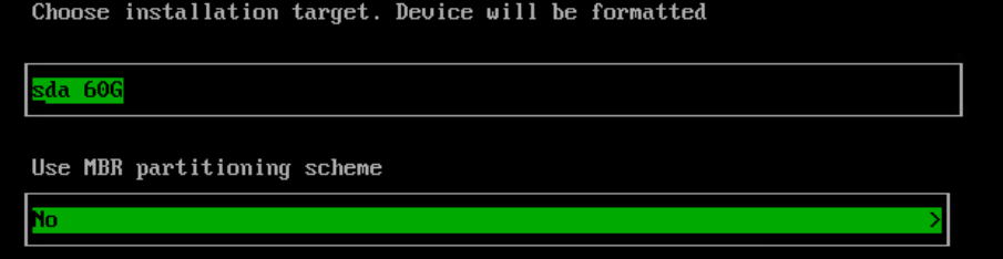
Select the Install target and optional MBR partitioning
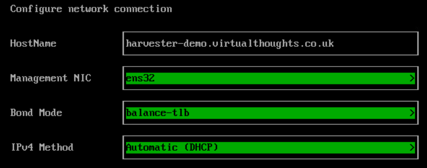
Configure the hostname, management nic and IP assignment options.
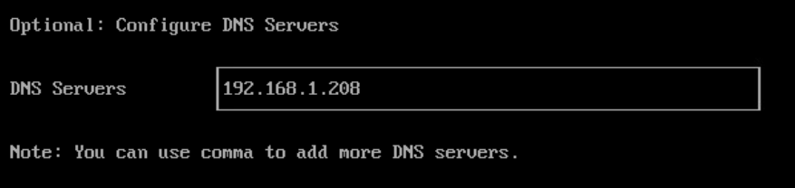
Configure the DNS config:
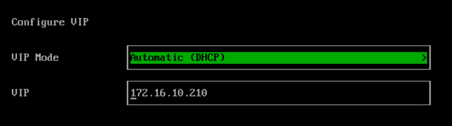
Configure the Harvester VIP. This is what we will use to access the Web UI. This can also be obtained via DHCP if desired.
Configure the cluster token, this is required if you want to add more nodes later on.
Configure the local Password:
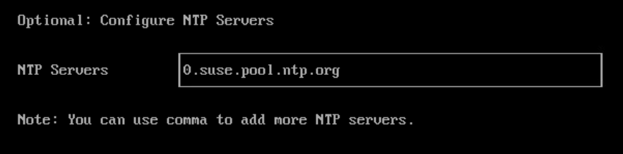
Configure the NTP server Address:
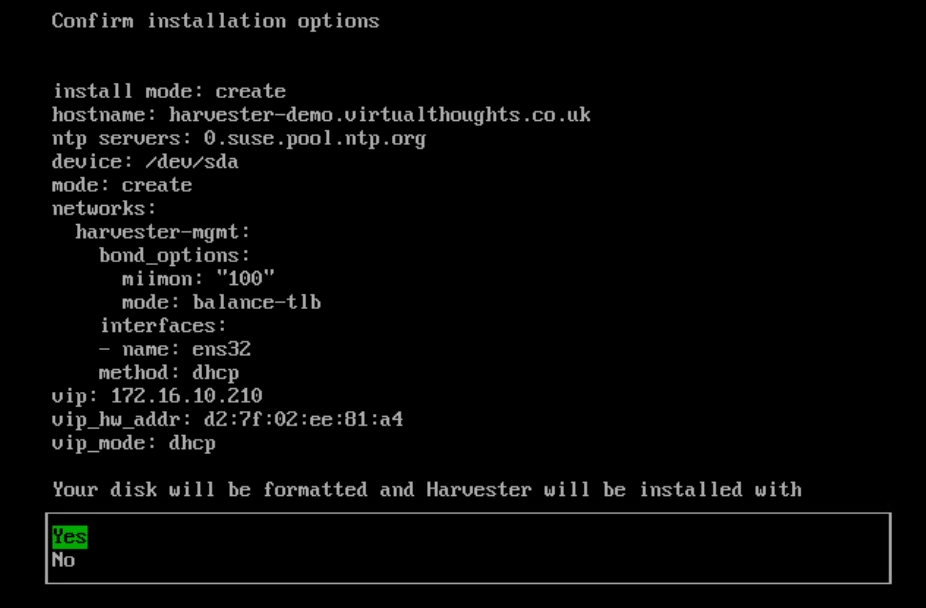
If desired, the subsequent options facilitate importing SSH keys, reading a remote config, etc which are optional. A summary will be presented before the install begins:
Proceed with the install.
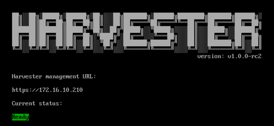
Note : After a reboot, it may take a few minutes before harvester reports as being in a ready state – Once it does, navigate to the reported management URL.
At which point you will be prompted to reset the admin password
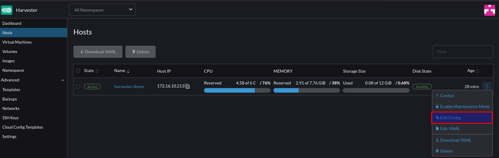
Step 5 – Configure VM Network
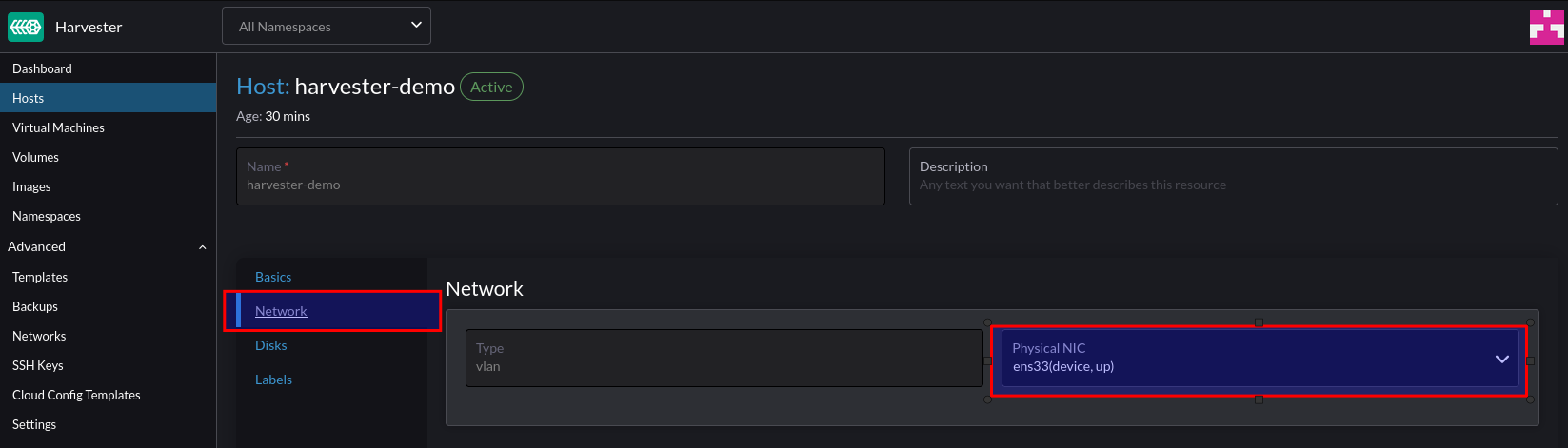
Once logged in to Harvester navigate to Hosts > Edit Config
Configure the secondary NIC to the VLAN network (our VM network)
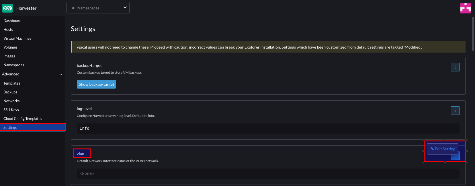
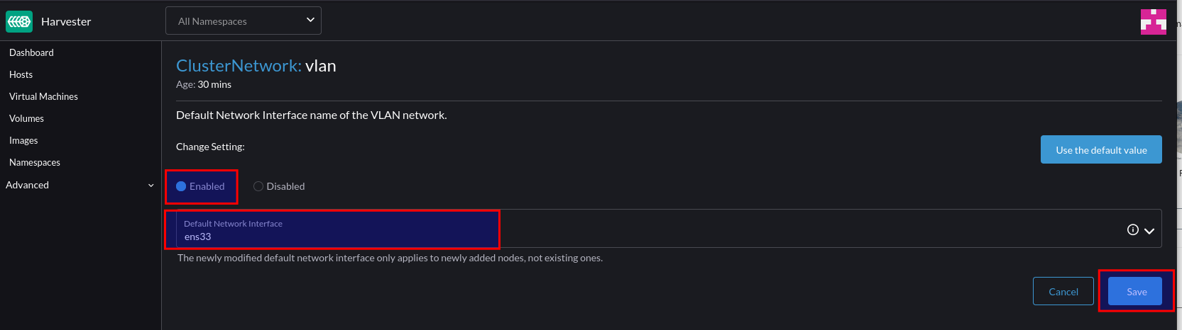
Navigate to Settings > VLAN > Edit
Click “Enable” and select the default interface to the secondary interface. This will be the default for any new nodes that join the cluster.
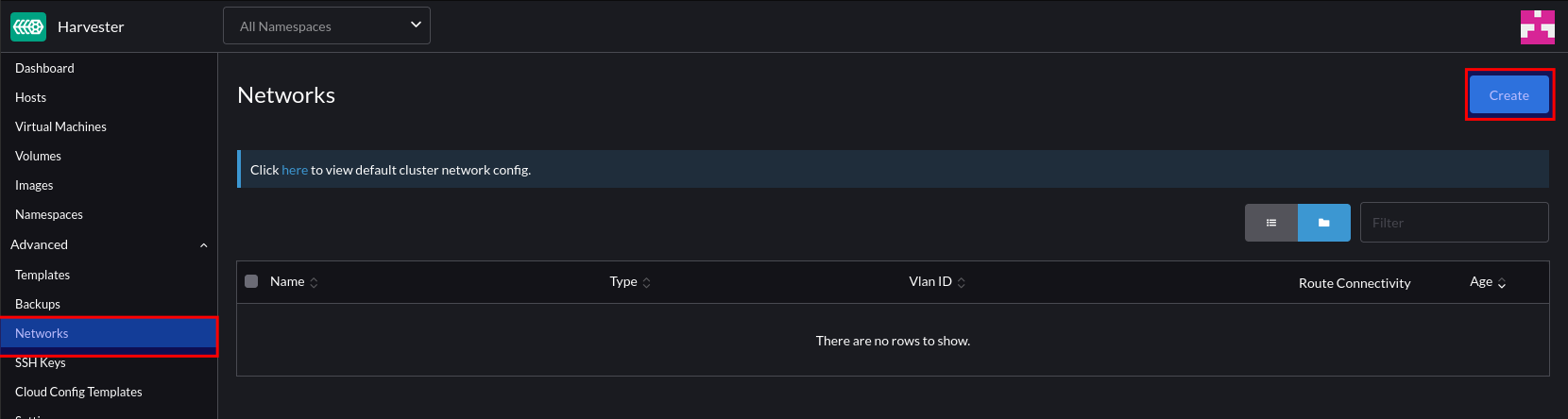
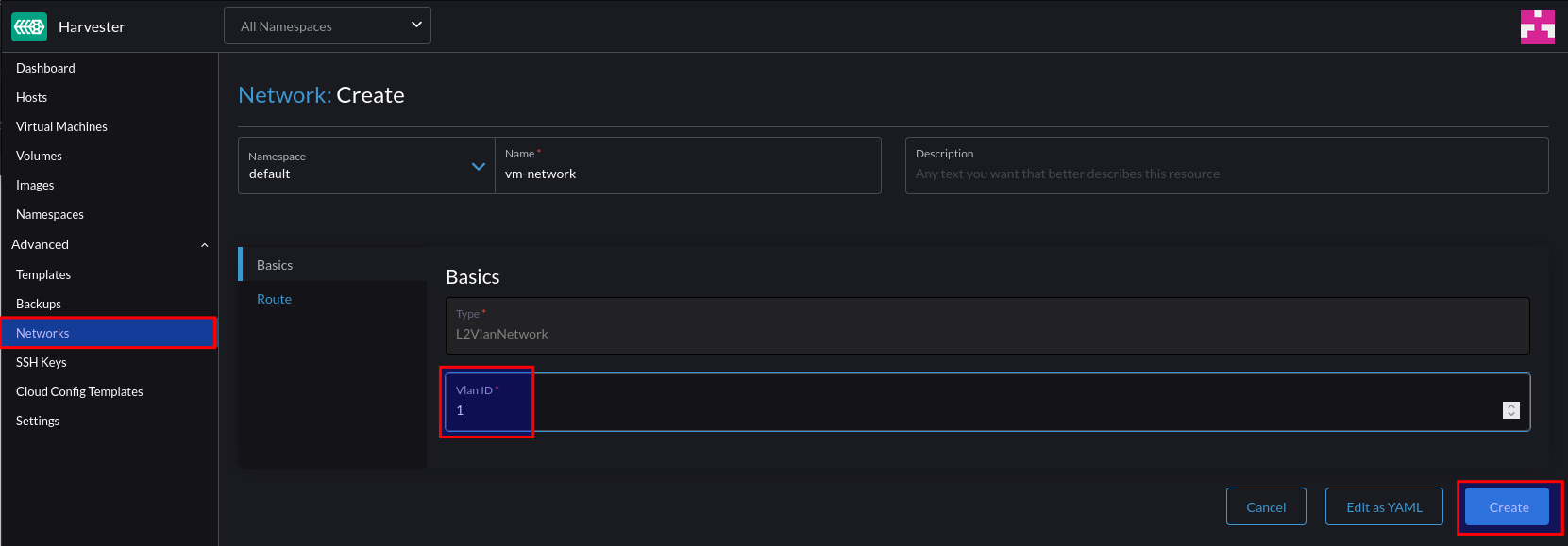
To create a network for our VM’s to reside in, select Network > Create:
Give this network a name and a VLAN ID. Note – you can supply VLAN ID 1 if you’re using the native/default VLAN.
Step 6 – Test VM Network
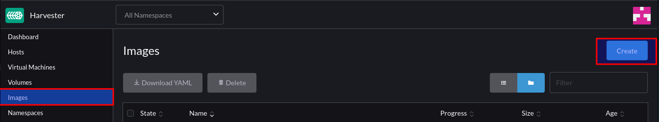
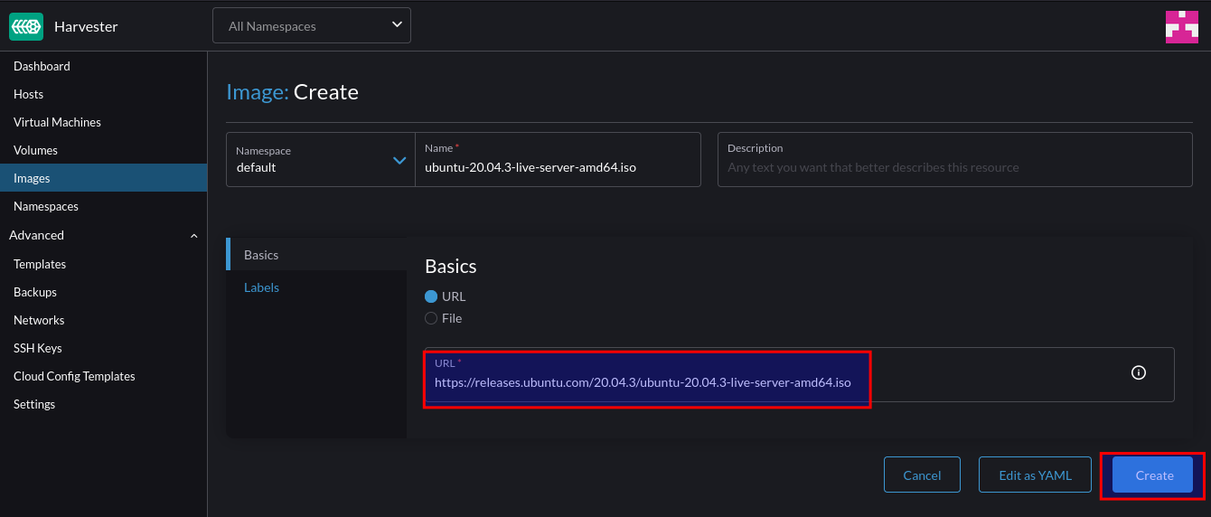
Firstly, create a new image:
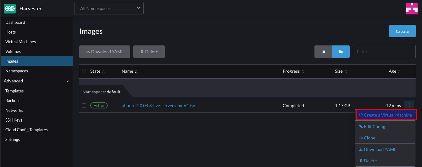
For this example, we can use an ISO image. After supplying the URL Harvester will download and store the image:
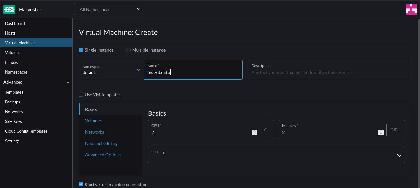
After downloading, we can create a VM from it:
Specify the VM specs (CPU and Mem)
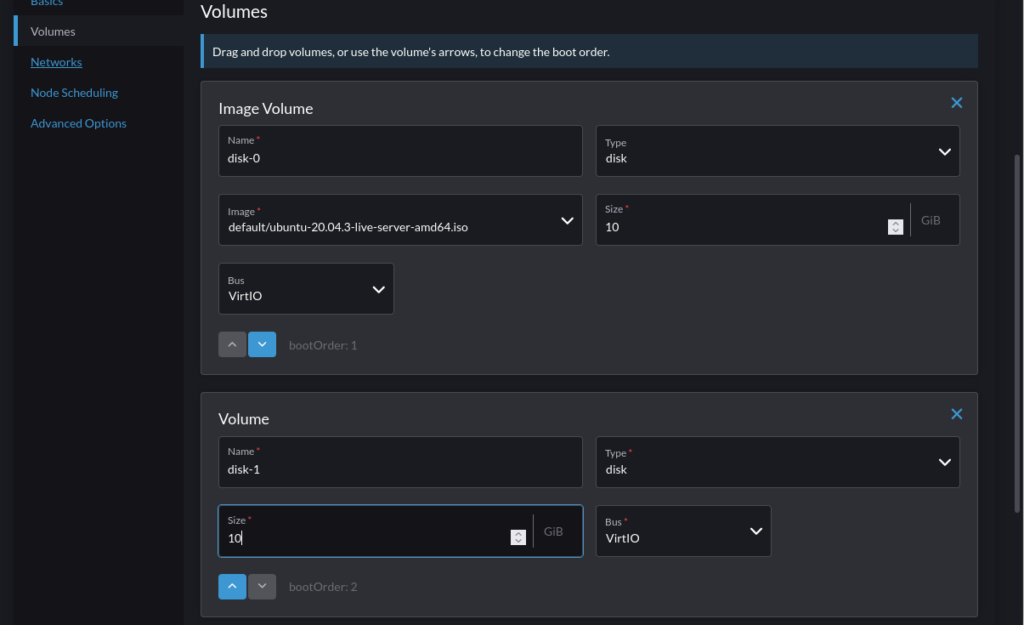
Under Volumes, add an additional volume to act as the installation target for the OS (Or leave if purely wanting to use a live ISO):
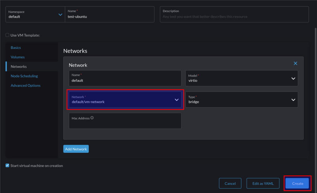
Under Networks, change the selection to the VM network that was previously created and click “Create”:
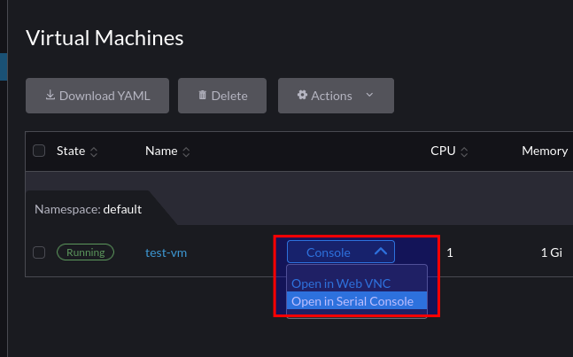
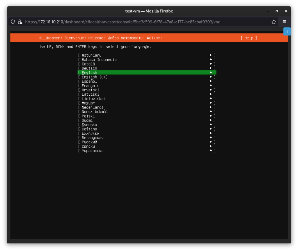
Once the VM is in running state, we can take a VNC console to it:
At which point we can interact with it as we would expect with any HCI solution: