Virtualisation, Storage and various other ramblings.

Author: David (Page 5 of 24)

Using the NSX-T CNI with RKE2

This post outlines the necessary steps to leverage the VMware NSX-T CNI with RKE2

1. Planning

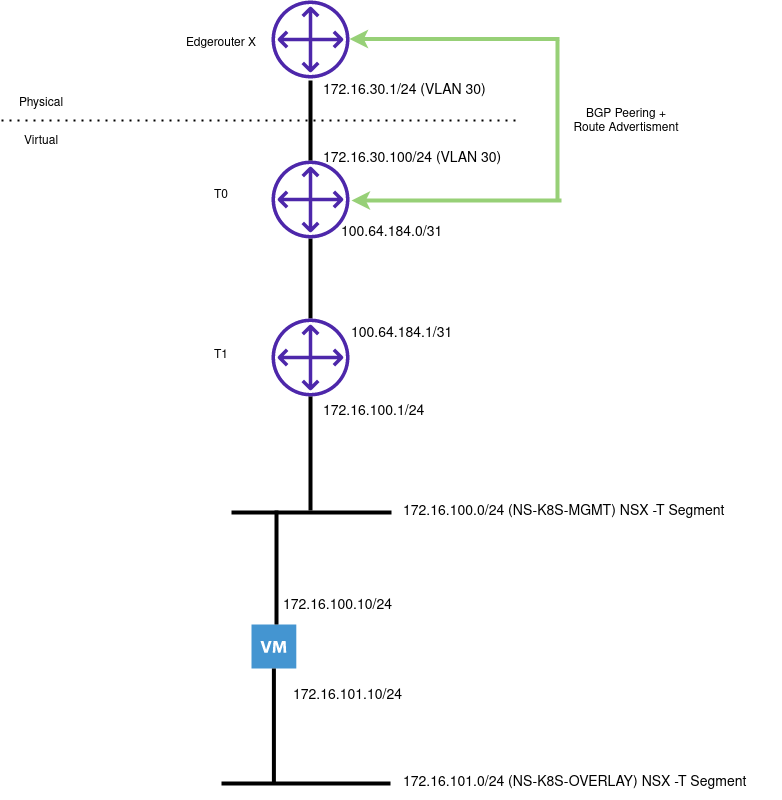
The following illustrates my Lab environment with a single node cluster:

General Considerations

If you have a new NSX-T environment, ensure you have (as a minimum) the following:

  • T0 Router
  • T1 Router
  • Edge Cluster
  • VLAN Transport Zone
  • Overlay Transport Zone
  • Route advertisement (BGP/OSPF) to the physical network

NSX Specific Considerations

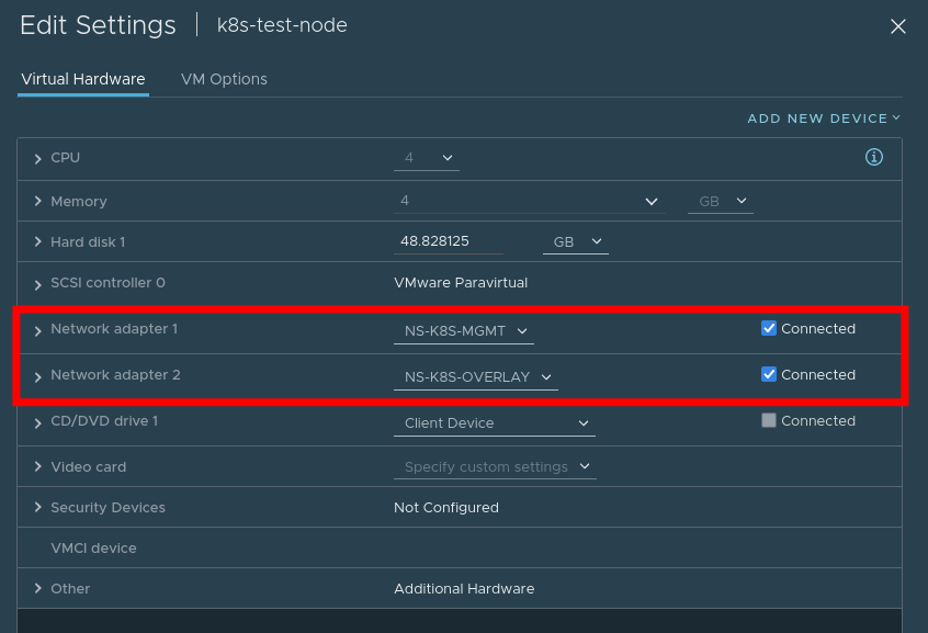
  • A network segment (or vds port) for management traffic (NS-K8S-MGMT in this example)
  • A network segment for overlay traffic (NS-K8S-OVERLAY)

Management traffic should be put on a routed network
Overlay traffic does not have to be on a routed network

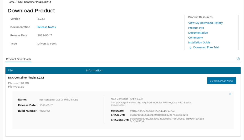
You will need to acquire and upload the ncp container image to a private repo:

This will contain the NCP image

2. Prepare NSX Objects

  • Create and retrieve the object ID’s for:
  • An IP Block for the Pods (this /16 will be divided into /24’s in our cluster)
  • An IP Pool for loadBalancer service types

3. Create VM

  • Create a VM with one nic attached to the Management network, and one attached to the Overlay network. Note, for ease you can configure NSX-T to provide DHCP services to both
  • Ensure Python is Installed (aka Python2)

4. Install RKE2

  • Create the following configuration file to instruct RKE2 not to auto-apply a CNI:
packerbuilt@k8s-test-node:~$ cat /etc/rancher/rke2/config.yaml 
cni:
  - none
  • Install RKE2
curl -sfL https://get.rke2.io | sh -
systemctl enable rke2-server.service
systemctl start rke2-server.service
# Wait a bit
export KUBECONFIG=/etc/rancher/rke2/rke2.yaml PATH=$PATH:/var/lib/rancher/rke2/bin
kubectl get nodes
  • You will notice some pods are in pending state – this is normal as these reside outside of the host networking namespace and we have yet to install a CNI

5. Install additional CNI binaries

  • NSX-T also requires access to the portmap CNI binary. this can be acquired by:
wget https://github.com/containernetworking/plugins/releases/download/v1.1.1/cni-plugins-linux-amd64-v1.1.1.tgz
  • Extract the contents to /opt/cni/bin/

6. Tag the overlay network port on the VM

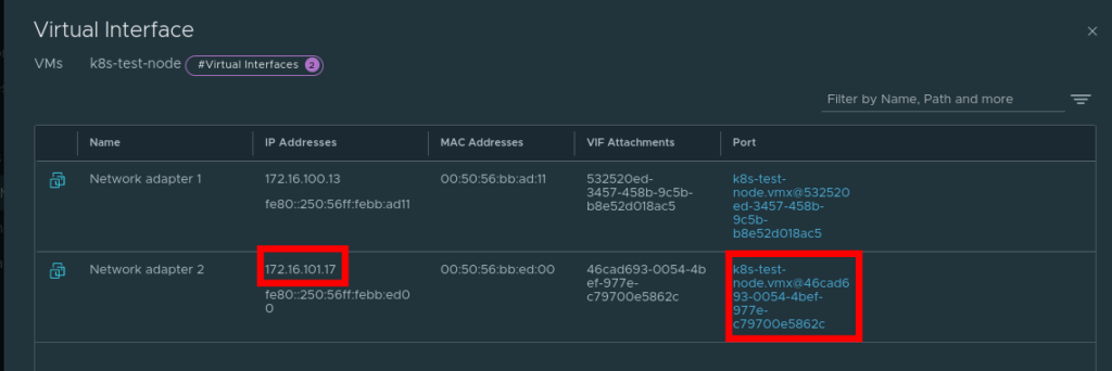
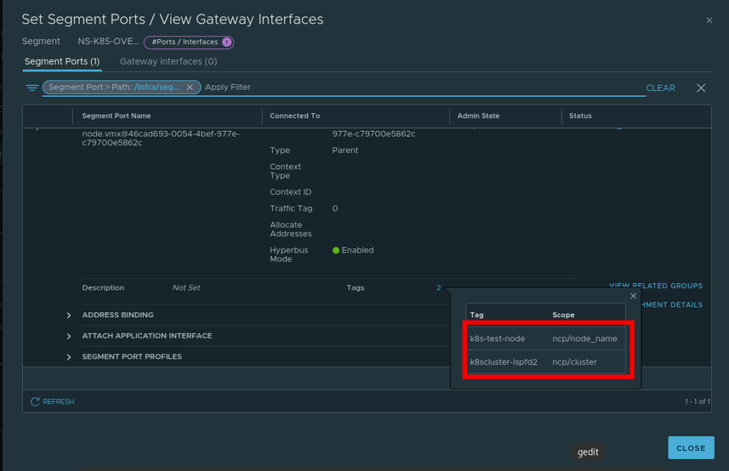
The NSX-T container plugin needs to identify the port used for container traffic. In the example above, this is the interface connection to our Overlay switch

img_1.png
  • In NSX-T navigate to Inventory -> Virtual Machines -> Select the VM
  • Select the port that’s connected to the overlay switch
  • Add the tags as appropriate

7. Download the NCP operator files

  • git clone https://github.com/vmware/nsx-container-plugin-operator
  • Change directory – cd /deploy/kubernetes/

8. Change the Operator yaml

  • Operator.yaml – replace where the image resides in your environment. Example:
            - name: NCP_IMAGE
              value: "core.harbor.virtualthoughts.co.uk/library/nsx-ncp-ubuntu:latest"

9. Change the Configmap yaml file

Which values to change will depend on your deployment topology, but as an example:

@@ -11,7 +11,7 @@ data:
 
     # If set to true, the logging level will be set to DEBUG instead of the
     # default INFO level.
-    #debug = False
+    debug = True


@@ -52,10 +52,10 @@ data:
     [coe]
 
     # Container orchestrator adaptor to plug in.
-    #adaptor = kubernetes
+    adaptor = kubernetes
 
     # Specify cluster for adaptor.
-    #cluster = k8scluster
+    cluster = k8scluster-lspfd2
 
     # Log level for NCP modules (controllers, services, etc.). Ignored if debug
     # is True
@@ -111,10 +111,10 @@ data:
     [k8s]
 
     # Kubernetes API server IP address.
-    #apiserver_host_ip = <None>
+    apiserver_host_ip = 172.16.100.13
 
     # Kubernetes API server port.
-    #apiserver_host_port = <None>
+    apiserver_host_port = 6443
 
     # Full path of the Token file to use for authenticating with the k8s API
     # server.
@@ -129,7 +129,7 @@ data:
     # Specify whether ingress controllers are expected to be deployed in
     # hostnework mode or as regular pods externally accessed via NAT
     # Choices: hostnetwork nat
-    #ingress_mode = hostnetwork
+    ingress_mode = nat
 
     # Log level for the kubernetes adaptor. Ignored if debug is True
     # Choices: NOTSET DEBUG INFO WARNING ERROR CRITICAL
@@ -254,7 +254,7 @@ data:
 
 
     # The OVS uplink OpenFlow port where to apply the NAT rules to.
-    #ovs_uplink_port = <None>
+    ovs_uplink_port = ens224
 
     # Set this to True if you want to install and use the NSX-OVS kernel
     # module. If the host OS is supported, it will be installed by nsx-ncp-
@@ -318,8 +318,11 @@ data:
     # [<scheme>://]<ip_adress>[:<port>]
     # If scheme is not provided https is used. If port is not provided port 80
     # is used for http and port 443 for https.
-    #nsx_api_managers = []
-
+    nsx_api_managers = 172.16.10.43
+    nsx_api_user = admin
+    nsx_api_password = SuperSecretPassword123!
+    insecure = true
+    
     # If True, skip fatal errors when no endpoint in the NSX management cluster
     # is available to serve a request, and retry the request instead
     #cluster_unavailable_retry = False
@@ -438,7 +441,7 @@ data:
     # support automatically creating the IP blocks. The definition is a comma
     # separated list: CIDR,CIDR,... Mixing different formats (e.g. UUID,CIDR)
     # is not supported.
-    #container_ip_blocks = []
+    container_ip_blocks = IB-K8S-PODS 
 
     # Resource ID of the container ip blocks that will be used for creating
     # subnets for no-SNAT projects. If specified, no-SNAT projects will use
@@ -451,7 +454,7 @@ data:
     # creating the ip pools. The definition is a comma separated list:
     # CIDR,IP_1-IP_2,... Mixing different formats (e.g. UUID, CIDR&IP_Range) is
     # not supported.
-    #external_ip_pools = []
+    external_ip_pools = IP-K8S-LB


@@ -461,7 +464,7 @@ data:
     # Name or ID of the top-tier router for the container cluster network,
     # which could be either tier0 or tier1. If policy_nsxapi is enabled, should
     # be ID of a tier0/tier1 gateway.
-    #top_tier_router = <None>
+    top_tier_router = T0
 
     # Option to use single-tier router for the container cluster network
     #single_tier_topology = False
@@ -472,13 +475,13 @@ data:
     # policy_nsxapi is enabled, it also supports automatically creating the ip
     # pools. The definition is a comma separated list: CIDR,IP_1-IP_2,...
     # Mixing different formats (e.g. UUID, CIDR&IP_Range) is not supported.
-    #external_ip_pools_lb = []
+    #external_ip_pools_lb = IP-K8S-LB
 
     # Name or ID of the NSX overlay transport zone that will be used for
     # creating logical switches for container networking. It must refer to an
     # already existing resource on NSX and every transport node where VMs
     # hosting containers are deployed must be enabled on this transport zone
-    #overlay_tz = <None>
+    overlay_tz = nsx-overlay-transportzone
 
 
     # Resource ID of the lb service that can be attached by virtual servers
@@ -500,11 +503,11 @@ data:
 
     # Resource ID of the firewall section that will be used to create firewall
     # sections below this mark section
-    #top_firewall_section_marker = <None>
+    top_firewall_section_marker = 0eee3920-1584-4c54-9724-4dd8e1245378
 
     # Resource ID of the firewall section that will be used to create firewall
     # sections above this mark section
-    #bottom_firewall_section_marker = <None>
+    bottom_firewall_section_marker = 3d67b13c-294e-4470-95db-7376cc0ee079


@@ -523,7 +526,7 @@ data:
 
     # Edge cluster ID needed when creating Tier1 router for loadbalancer
     # service. Information could be retrieved from Tier0 router
-    #edge_cluster = <None>
+    edge_cluster = 726530a3-a488-44d5-aea6-7ee21d178fbc

10. Apply the manifest files

kubectl apply -f /nsx-container-plugin-operator/deploy/kubernetes/*

You should see both the operator and NCP workloads manifest

root@k8s-test-node:/home/packerbuilt/nsx-container-plugin-operator/deploy/kubernetes# kubectl get po -n nsx-system
NAME                       READY   STATUS    RESTARTS   AGE
nsx-ncp-5666788456-r4nzb   1/1     Running   0          4h31m
nsx-ncp-bootstrap-6rncw    1/1     Running   0          4h31m
nsx-node-agent-6rstw       3/3     Running   0          4h31m
root@k8s-test-node:/home/packerbuilt/nsx-container-plugin-operator/deploy/kubernetes# kubectl get po -n nsx-system-operator
NAME                               READY   STATUS    RESTARTS   AGE
nsx-ncp-operator-cbcd844d4-tn4pm   1/1     Running   0          4h31m

Pods should be transitioning to running state, and loadbalancer services will be facilitated by NSX

root@k8s-test-node:/home/packerbuilt/nsx-container-plugin-operator/deploy/kubernetes# kubectl get svc
NAME            TYPE           CLUSTER-IP     EXTERNAL-IP     PORT(S)        AGE
kubernetes      ClusterIP      10.43.0.1      <none>          443/TCP        4h34m
nginx-service   LoadBalancer   10.43.234.41   172.16.102.24   80:31848/TCP   107m
root@k8s-test-node:/home/packerbuilt/nsx-container-plugin-operator/deploy/kubernetes# curl 172.16.102.24
<!DOCTYPE html>
<html>
<head>
<title>Welcome to nginx!</title>
<style>
    body {
      ......
    }

The end result is a topology where every namespace has its own T1 router, advertised to T0:

Evaluating Harvester in vSphere

Disclaimer – The use of nested virtualisation is not a supported topology

Harvester is an open-source HCI solution aimed at managing Virtual Machines, similar to vSphere and Nutanix, with key differences including (but not limited to):

  • Fully Open Source
  • Leveraging Kubernetes-native technologies
  • Integration with Rancher

Testing/evaluating any hyperconverged solution can be difficult – It usually requires having dedicated hardware as these solutions are designed to work directly on bare metal. However, we can circumvent this by leveraging nested virtualisation – something which may be familiar with a lot of homelabbers (myself included) – which involves using an existing virtualisation solution provision workloads that also leverage virtualisation technology.

Step 1 – Planning

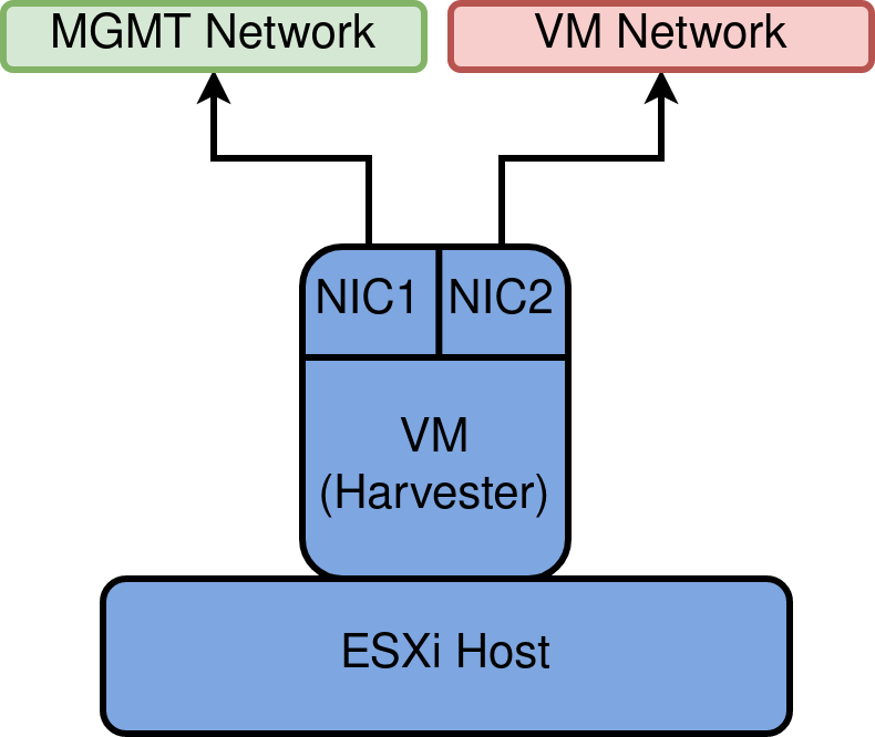
To mimic what a production-like system may look like, two NICs will be leveraged – one that facilitates management traffic, and the other for Virtual Machine traffic, as depicted below

MGMT network and VM Network will manifest as VDS Port groups.

Also, download and make available the latest ISO for harvester

Step 2 – Create vDS Port Groups

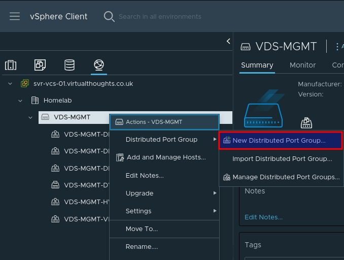
It is highly recommended to create new Distributed Port groups for this exercise, mainly because of the configuration we will be applying in the next step.

Create a new vDS Port Group:

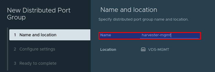
Give the port group a name, such as harvester-mgmt

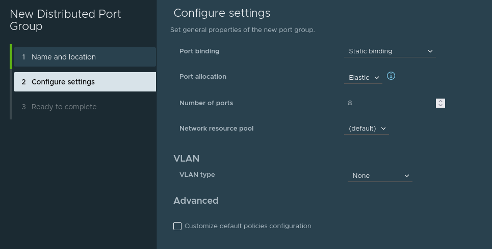
Adjust any configuration (ie VLAN ID) to match your environment (if required). Or accept the defaults:

Repeat this process to create the harvester-vm Port group. We should now have two port groups:

  • harvester-mgmt
  • harvester-vm

Step 3 – Enable MAC learning on Port groups [Critical]

William Lam has an excellent post on how to accomplish this. This is required for Harvester (or any hypervisor) to function correctly when operating in a nested environment.

Set-MacLearn -DVPortgroupName @("harvester-mgmt") -EnableMacLearn $true -EnablePromiscuous $false -EnableForgedTransmit $true -EnableMacChange $false

Set-MacLearn -DVPortgroupName @("harvester-vm") -EnableMacLearn $true -EnablePromiscuous $false -EnableForgedTransmit $true -EnableMacChange $false

Step 4 – Creating a Harvester VM

Our Harvester VM will operate like any other VM, with some important differences. In vSphere, go through the standard VM creation wizard to specify the Host/Datastore options. When presented with the OS type, select Other Linux (64 bit).

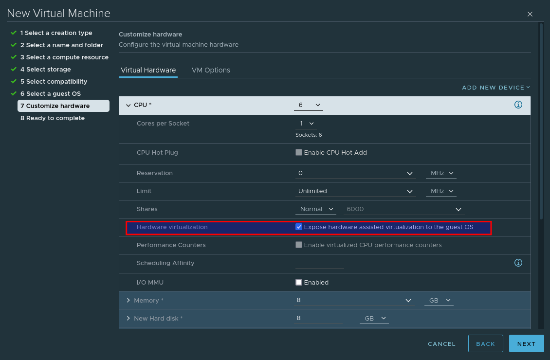
When customising the hardware, select Expose hardware assisted virtualization to the guest OS – This is crucial, as without this selected Harvester will not install.

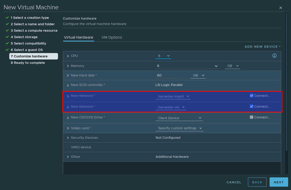
Add an additional network card so that our VM leverages both previously created port groups:

And finally, mount the Harvester ISO image.

Step 4 – Install Harvester

Power on the VM and providing the ISO is mounted and connected, you should be presented with the install screen. As this is the first node, select create a new Harvester Cluster

Select the Install target and optional MBR partitioning

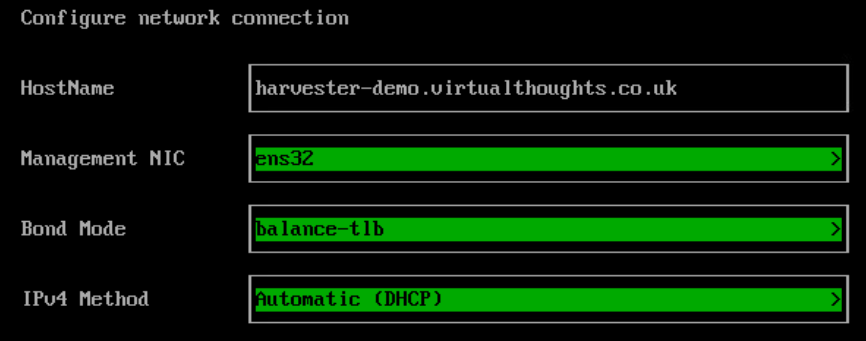
Configure the hostname, management nic and IP assignment options.

Configure the DNS config:

Configure the Harvester VIP. This is what we will use to access the Web UI. This can also be obtained via DHCP if desired.

Configure the cluster token, this is required if you want to add more nodes later on.

Configure the local Password:

Configure the NTP server Address:

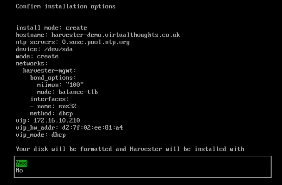
If desired, the subsequent options facilitate importing SSH keys, reading a remote config, etc which are optional. A summary will be presented before the install begins:

Proceed with the install.

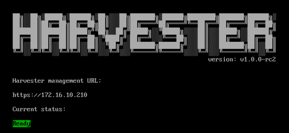
Note : After a reboot, it may take a few minutes before harvester reports as being in a ready state – Once it does, navigate to the reported management URL.

At which point you will be prompted to reset the admin password

Step 5 – Configure VM Network

Once logged in to Harvester navigate to Hosts > Edit Config

Configure the secondary NIC to the VLAN network (our VM network)

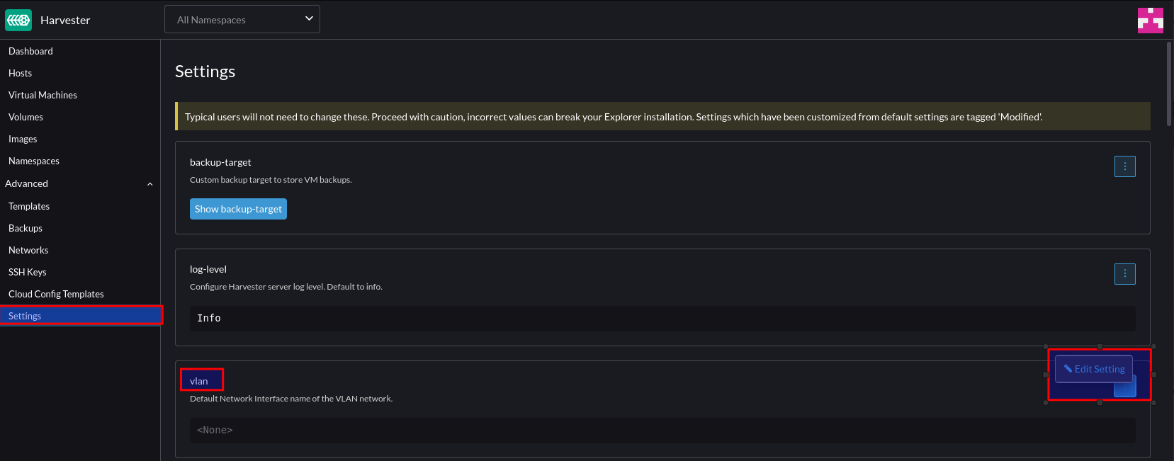
Navigate to Settings > VLAN > Edit

Click “Enable” and select the default interface to the secondary interface. This will be the default for any new nodes that join the cluster.

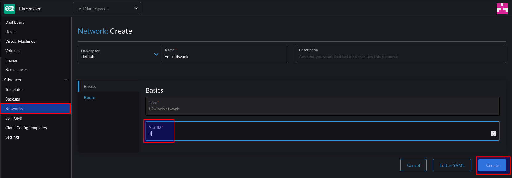
To create a network for our VM’s to reside in, select Network > Create:

Give this network a name and a VLAN ID. Note – you can supply VLAN ID 1 if you’re using the native/default VLAN.

Step 6 – Test VM Network

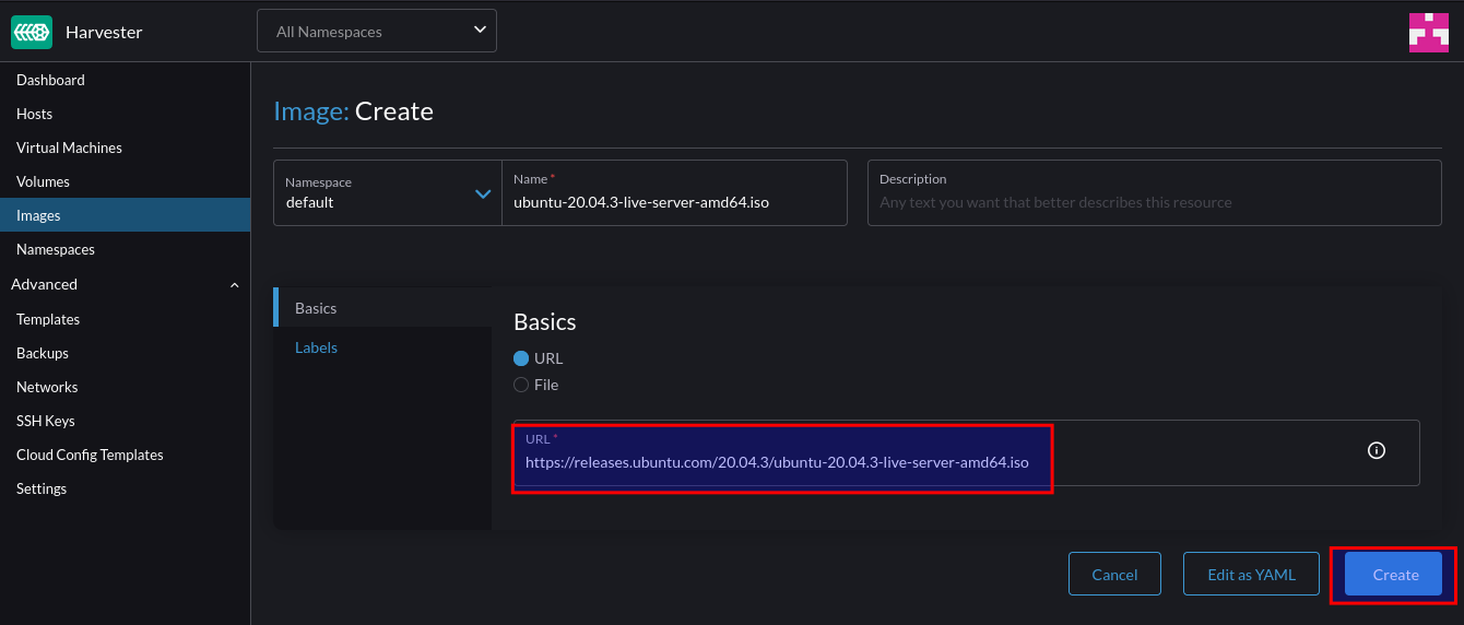
Firstly, create a new image:

For this example, we can use an ISO image. After supplying the URL Harvester will download and store the image:

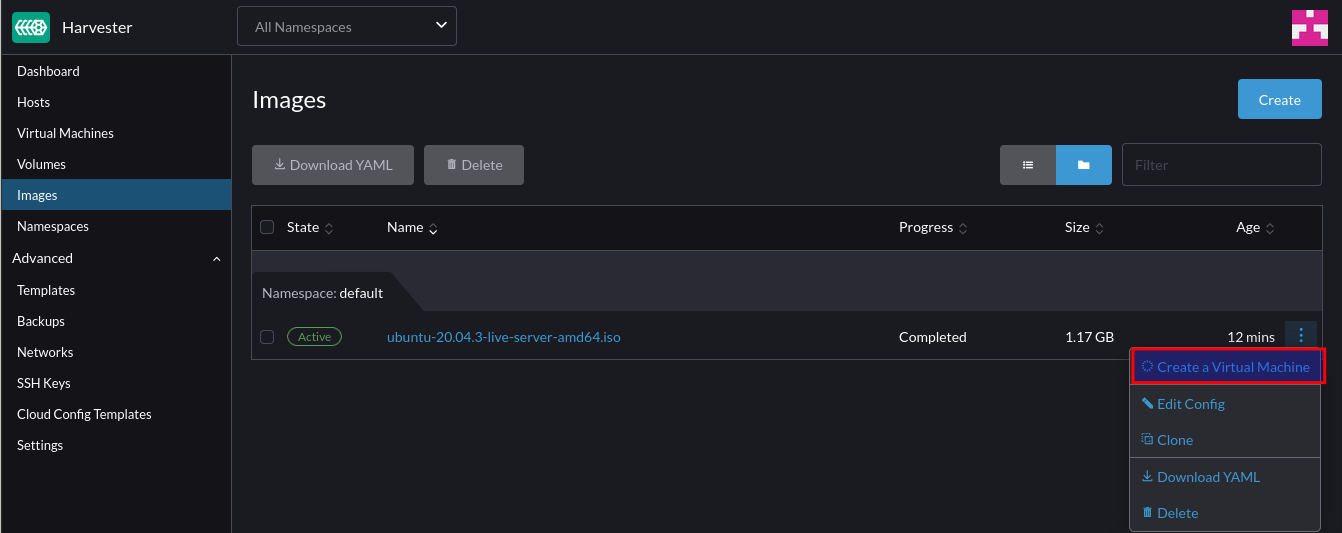
After downloading, we can create a VM from it:

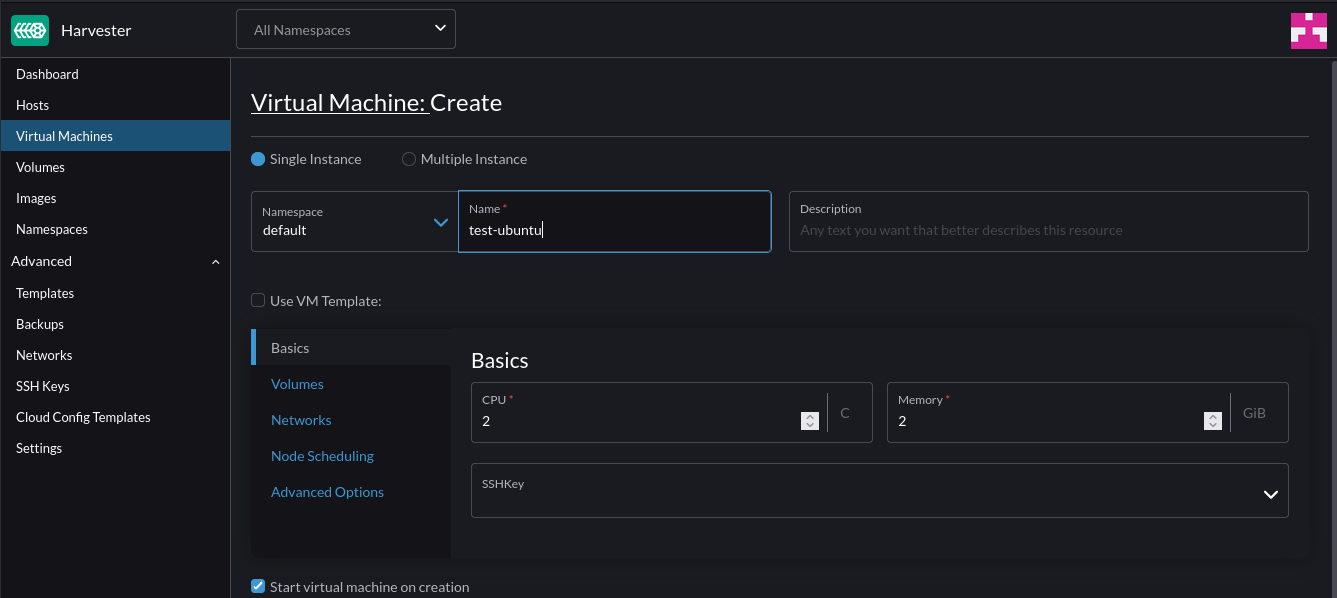
Specify the VM specs (CPU and Mem)

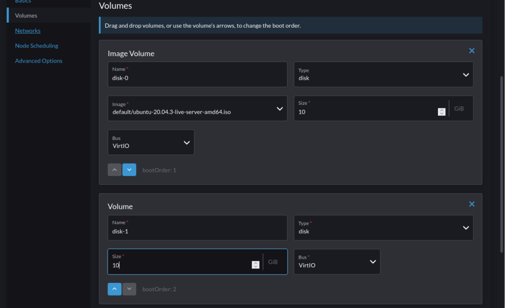
Under Volumes, add an additional volume to act as the installation target for the OS (Or leave if purely wanting to use a live ISO):

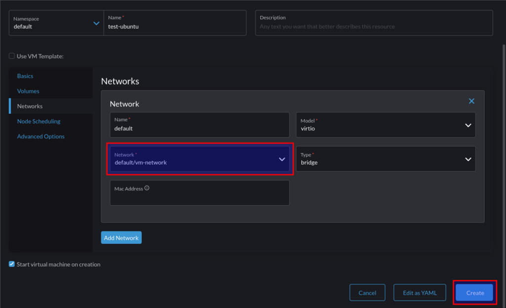
Under Networks, change the selection to the VM network that was previously created and click “Create”:

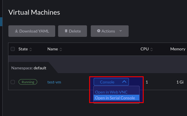
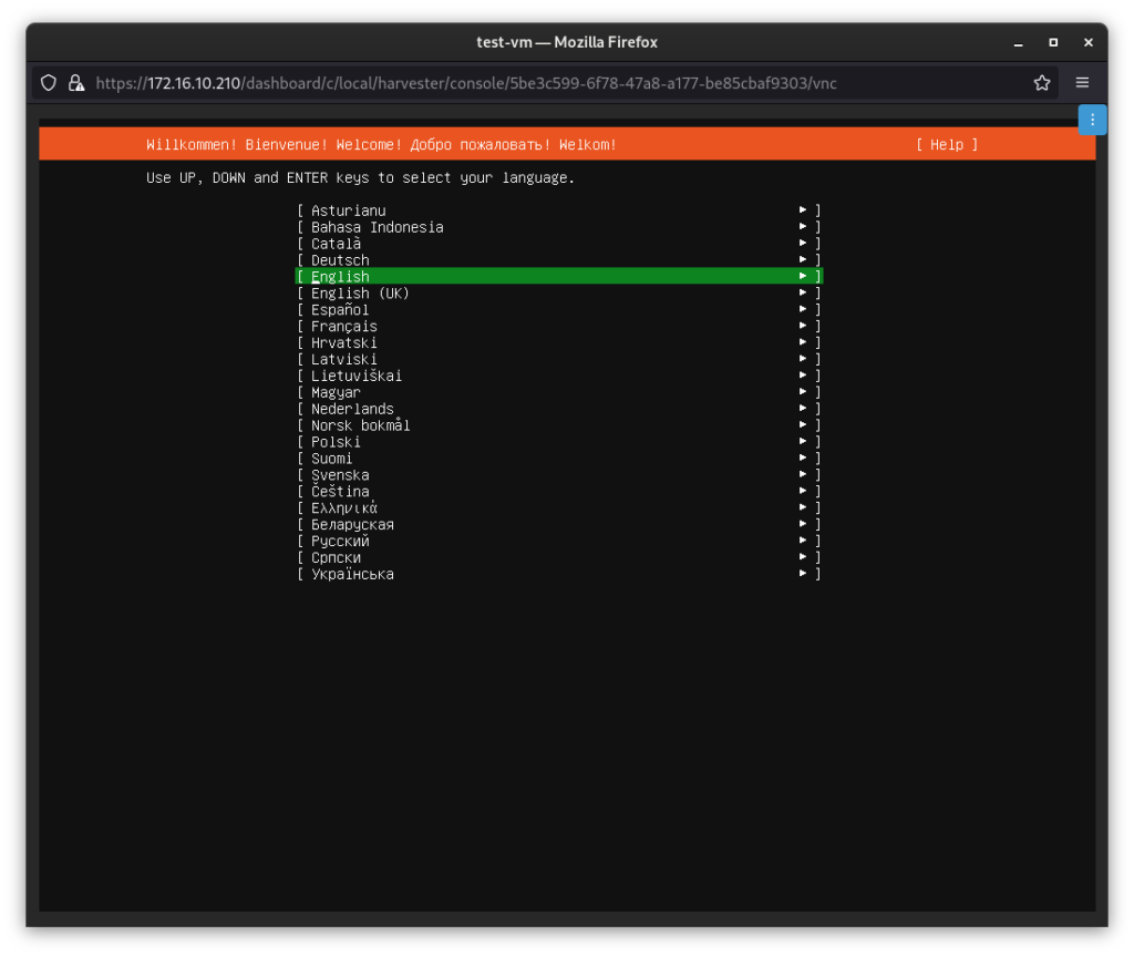
Once the VM is in running state, we can take a VNC console to it:

At which point we can interact with it as we would expect with any HCI solution:

Taking a Modular Approach to my Homelab with Pulumi

Architecture

After reviewing the key components of my lab environment, I translated these into the Pulumi stacks as illustrated in the diagram below. Pulumi has a blog post about the benefits of adopting multiple stacks and I found organising my homelab this way enables greater flexibility and organisation. I can also use stacks as a “template” to further build out my lab environment, for example, repeating the “Tools-Cluster” stack to add additional clusters.

The main objectives are:

  • Create a 3 node, K3s cluster utilising vSphere VM’s
  • Install Metallb, Rancher and Cert-Manager into this cluster
  • Using Rancher, create an RKE2 cluster to accommodate shared tooling services, ie:
    • Rancher Monitoring Stack (Prometheus, Grafana, Alertmanager, etc)
    • Hashicorp Vault
    • etc

Building

Each stack contains the main Pulumi code, a YAML file to hold various variables to influence parameters such as VM names, Networking config, etc.

├── rancher-application
│   ├── Assets
│   │   └── metallb
│   │       └── metallb-values.yaml
│   ├── go.mod
│   ├── go.sum
│   ├── main.go
│   ├── Pulumi.dev.yaml
│   └── Pulumi.yaml
├── rancher-management-cluster
│   ├── Assets
│   │   ├── metadata.yaml
│   │   └── userdata.yaml
│   ├── go.mod
│   ├── go.sum
│   ├── main.go
│   ├── Pulumi.dev.yaml
│   └── Pulumi.yaml
└── rancher-tools-cluster
    ├── Assets
    │   └── userdata.yaml
    ├── go.mod
    ├── go.sum
    ├── main.go
    ├── Pulumi.dev.yaml
    └── Pulumi.yaml

Each stack has a corresponding assets directory which contains supporting content for a number of components:

  • Rancher Application – Values.yaml to influence the metallb L2 VIP addresses
  • Rancher Management Cluster – Userdata and Metadata to send to the created VM’s, including bootstrapping K3s
  • Rancher Tools Cluster – Userdata to configure the local registry mirror

Rancher Management Cluster Stack

This is the first stack that needs to be created and is relatively simple in terms of its purpose. The metadata.yaml contains a template for defining cloud-init metadata for the nodes:

network:
  version: 2
  ethernets:
    ens192:
      dhcp4: false
      addresses:
        - $node_ip
      gateway4: $node_gateway
      nameservers:
        addresses:
          - $node_dns
local-hostname: $node_hostname
instance-id: $node_instance

userdata.yaml contains k3s-specific configuration pertaining to my local registry mirror as well a placeholder for the K3S bootstrapping process, $runcmd.

#cloud-config
write_files:
  - path: /etc/rancher/k3s/registries.yaml
    content: |
      mirrors:
        docker.io:
          endpoint:
            - "http://172.16.10.208:5050"
runcmd:
  - $runcmd

Creating the VM’s leverages the existing vSphere Pulumi provider, seeding the nodes with cloud-init user/metadata which also instantiates K3s.

userDataEncoded := base64.StdEncoding.EncodeToString([]byte(strings.Replace(string(userData), "$runcmd", k3sRunCmdBootstrapNode, -1)))

				vm, err := vsphere.NewVirtualMachine(ctx, vmPrefixName+strconv.Itoa(i+1), &vsphere.VirtualMachineArgs{
					Memory:         pulumi.Int(6144),
					NumCpus:        pulumi.Int(4),
					DatastoreId:    pulumi.String(datastore.Id),
					Name:           pulumi.String(vmPrefixName + strconv.Itoa(i+1)),
					ResourcePoolId: pulumi.String(resourcePool.Id),
					GuestId:        pulumi.String(template.GuestId),
					Clone: vsphere.VirtualMachineCloneArgs{
						TemplateUuid: pulumi.String(template.Id),
					},
					Disks: vsphere.VirtualMachineDiskArray{vsphere.VirtualMachineDiskArgs{
						Label: pulumi.String("Disk0"),
						Size:  pulumi.Int(50),
					}},
					NetworkInterfaces: vsphere.VirtualMachineNetworkInterfaceArray{vsphere.VirtualMachineNetworkInterfaceArgs{
						NetworkId: pulumi.String(network.Id),
					},
					},
					ExtraConfig: pulumi.StringMap{
						"guestinfo.metadata.encoding": pulumi.String("base64"),
						"guestinfo.metadata":          pulumi.String(metaDataEncoded),
						"guestinfo.userdata.encoding": pulumi.String("base64"),
						"guestinfo.userdata":          pulumi.String(userDataEncoded),
					},
				},
				)
				if err != nil {
					return err
				}

The first node initiates the K3s cluster creation process. Subsequent nodes have their $rucmd manipulated by identifying the first node’s IP address and using that to join the cluster:

userDataEncoded := vms[0].DefaultIpAddress.ApplyT(func(ipaddress string) string {

					runcmd := fmt.Sprintf(k3sRunCmdSubsequentNodes, ipaddress)
					return base64.StdEncoding.EncodeToString([]byte(strings.Replace(string(userData), "$runcmd", runcmd, -1)))
				}).(pulumi.StringOutput)

				vm, err := vsphere.NewVirtualMachine(ctx, vmPrefixName+strconv.Itoa(i+1), &vsphere.VirtualMachineArgs{
					Memory:         pulumi.Int(6144),

Rancher Application Stack

This stack makes extensive use of the (currently experimental) Helm Release Resource as well as the cert-manager package from the Pulumi Registry

For example, creating the Metallb config map based on the aforementioned asset file:

		metallbConfigmap, err := corev1.NewConfigMap(ctx, "metallb-config", &corev1.ConfigMapArgs{
			Metadata: &metav1.ObjectMetaArgs{
				Namespace: metallbNamespace.Metadata.Name(),
			},
			Data: pulumi.StringMap{
				"config": pulumi.String(metallbConfig),
			},
		})

And the Helm release:

		_, err = helm.NewRelease(ctx, "metallb", &helm.ReleaseArgs{
			Chart:     pulumi.String("metallb"),
			Name:      pulumi.String("metallb"),
			Namespace: metallbNamespace.Metadata.Name(),
			RepositoryOpts: helm.RepositoryOptsArgs{
				Repo: pulumi.String("https://charts.bitnami.com/bitnami"),
			},
			Values: pulumi.Map{"existingConfigMap": metallbConfigmap.Metadata.Name()},
		})

And for Rancher:

		_, err = helm.NewRelease(ctx, "rancher", &helm.ReleaseArgs{
			Chart:     pulumi.String("rancher"),
			Name:      pulumi.String("rancher"),
			Namespace: rancherNamespace.Metadata.Name(),
			RepositoryOpts: helm.RepositoryOptsArgs{
				Repo: pulumi.String("https://releases.rancher.com/server-charts/latest"),
			},
			Values: pulumi.Map{
				"hostname":           pulumi.String(rancherUrl),
				"ingress.tls.source": pulumi.String("secret"),
			},
			Version: pulumi.String(rancherVersion),
		}, pulumi.DependsOn([]pulumi.Resource{certmanagerChart, rancherCertificate}))

As I used an existing secret for my TLS certificate I had to create a cert-manager cert object, for which there are a number of options that I experimented with:

1. Read a file

Similarly to the metallb config, A file could be read that contained the YAML to create the Custom Resource type, although this was a feasible approach, I wanted something that was less error-prone.

2. Use the API extension type

The Pulumi Kubernetes provider enables the provisioning of the type NewCustomResource. For my requirements, this is an improvement over simply reading a YAML file, however, anything beyond the resources metadata isn’t strongly typed

rancherCertificate, err := apiextensions.NewCustomResource(ctx, "rancher-cert", &apiextensions.CustomResourceArgs{
			ApiVersion: pulumi.String("cert-manager.io/v1"),
			Kind:       pulumi.String("Certificate"),
			Metadata: &metav1.ObjectMetaArgs{
				Name:      pulumi.String("tls-rancher-ingress"),
				Namespace: pulumi.String(rancherNamespaceName),
			},
			OtherFields: kubernetes.UntypedArgs{
				"spec": map[string]interface{}{
					"secretName": "tls-rancher-ingress",
					"commonName": "rancher.virtualthoughts.co.uk",
					"dnsNames":   []string{"rancher.virtualthoughts.co.uk"},
					"issuerRef": map[string]string{
						"name": "letsencrypt-staging",
						"kind": "ClusterIssuer",
					},
				},
			},
		}, pulumi.DependsOn([]pulumi.Resource{certmanagerChart, certmanagerIssuers}))

3. Use crd2pulumi

crd2pulumi is used to generate typed CustomResources based on Kubernetes CustomResourceDefinitions, I took the cert-manager CRD’s and ran it through this tool, uploaded to a repo and repeated the above process:

import (
	certmanagerresource "github.com/david-vtuk/cert-manager-crd-types/types/certmanager/certmanager/v1"
        ...
        ...
)
	rancherCertificate, err := certmanagerresource.NewCertificate(ctx, "tls-rancher-ingress", &certmanagerresource.CertificateArgs{
			ApiVersion: pulumi.String("cert-manager.io/v1"),
			Kind:       pulumi.String("Certificate"),
			Metadata: &metav1.ObjectMetaArgs{
				Name:      pulumi.String("tls-rancher-ingress"),
				Namespace: pulumi.String(rancherNamespaceName),
			},
			Spec: &certmanagerresource.CertificateSpecArgs{
				CommonName: pulumi.String(rancherUrl),
				DnsNames:   pulumi.StringArray{pulumi.String(rancherUrl)},
				IssuerRef: certmanagerresource.CertificateSpecIssuerRefArgs{
					Kind: leProductionIssuer.Kind,
					Name: leProductionIssuer.Metadata.Name().Elem(),
				},
				SecretName: pulumi.String("tls-rancher-ingress"),
			},
		})

Much better!

Tools Cluster Stack

Comparatively, this is the simplest of all the Stacks. Using the Rancher2 Pulumi Package makes it pretty trivial to build out new clusters and install apps:

_, err = rancher2.NewClusterV2(ctx, "tools-cluster", &rancher2.ClusterV2Args{
			CloudCredentialSecretName: cloudcredential.ID(),
			KubernetesVersion:         pulumi.String("v1.21.6+rke2r1"),
			Name:                      pulumi.String("tools-cluster"),
			//DefaultClusterRoleForProjectMembers: pulumi.String("user"),
			RkeConfig: &rancher2.ClusterV2RkeConfigArgs{

.........
}

				monitoring, err := rancher2.NewAppV2(ctx, "monitoring", &rancher2.AppV2Args{
					ChartName: pulumi.String("rancher-monitoring"),
					ClusterId: cluster.ClusterV1Id,
					Namespace: pulumi.String("cattle-monitoring-system"),
					RepoName:  pulumi.String("rancher-charts"),
				}, pulumi.DependsOn([]pulumi.Resource{clusterSync}))

« Older posts Newer posts »

© 2024 Virtual Thoughts

Theme by Anders NorenUp ↑

Social media & sharing icons powered by UltimatelySocial
RSS
Twitter
Visit Us
Follow Me